
Page 66 - APPLIED PROCESS DESIGN FOR CHEMICAL AND PETROCHEMICAL PLANTS, Volume 1, 3rd Edition
P. 66
Fluid Flow 53
- ~~~~
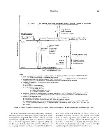
P = p’+ pbr Any Pressure Level Above Atmospheric (gauge or absolute = (gauge) I. [barometer))
I Gauge Pressure,
P’ Above Reference
Sea Level Standard li Atmospheric Pressure
760 mm Hg abs. or
- L A \. I’ Local Barometric Pressure, Pbr
Atmospheric Pressure (pbr), varies with Geographical Altitude Location, called
0 psig 0
Vacuum (Gauge)
Below
srometricl Atmospheric
‘essure or Below a
Standard
I Barometer
Arbitrary Pressure Level
eeemae
Absolute Pressure
is Above Referenke
Measurement of Absolute Zero
- Absolute Zero Pressure I
0 psia
(Perfect or Absolute Vacuum)
also, Absolute Reference Level
Notes:
1. At $rea level, barometric pressure = 14.696 poundslsq. in. absolute, or 760 mm of mercury, referred to as “Stan-
dard.” This is also 0 poundslsq. in. gauge for that location.
2. Absolute zero pressure is absolute vacuum. This is (9 psia, also known as 29.92 inches of mercury below at-
mospheric pressure, or 33.931 feet of water below atmospheric, all referenced at sea level.
3. Important equivalents: 1 atmospheric pressure at sea level =
(a) 14.696 psia
(b) 33.931 +et of water (at 60°F)
(c) 29.921 inches mercury (at 32°F)
(d) 760 fnm H, (at 32°F)
(e) 1.0332 ki1ogramk.q. centimeter
(f) 10,332.27 kilogram/sq. meter
4. Barometric pressure for altitudes above “standard“ sea level are given in the appendix. These correct values
must be used wherever the need for the local absolute barometric pressure is involved in pressure calculations.
5. Vacuum is expressed as either
(a) Inches (or millimeters) vacuum below atpospheric or local barometric, or
(b) Inches vacuum absolute, above absolute zero pressure or perfect vacuum.
(c) For example, at sea level of 29.921 in Hg abs. barometer;(l) IO’ vacuum is a gauge term, indicating 10” of mer-
cury below local barometric pressure; (2) 10” vacuum (gauge) is equivalent to 29.921” Hg abs. - 10” = 19.921” Hg
abs. vacuum.
Figure 2-1. Pressure level references. Adapted by permission from Crane Go., Technical Paper #470, Engineering Div*, 1957.
See nomenclature for definition of symbols and units. tion factor one-fourth that of the Darcy factor. Care
The units presented are English engineering units, unless should be observed; otherwise, the friction loss calcula-
a conversion is required. The friction factor is the only tions for flow of liquids or gases will be too low, but not
experimental variable that must be determined by refer- necessarily by a straight one-fourth factor. Also, it is
ence to the above equations and it is represented by Fig- important to note that the Figure 2-3 presented here is
ure 2-3. Note that this may sometimes be referred to as the friction chart recommended and consistent with the
the Fanning formula, and may be modified to yield a fric- engineering data of the Hydraulic Institute [2].