
Page 334 - Applied Process Design For Chemical And Petrochemical Plants Volume II
P. 334
Packed Towers 323
1. High cost/ft3 of space where p = liquid viscosity, cp
2. Easy plugging by solid particles p~ = liquid density, lb/cu ft3
3. Importance of uniform liquid distribution across the pv = vapor density, lb/ft3
packing If liquid viscosity is less than 0.15 cp, use constant 0.53
4. System operating under pressure [ 1531 or vacuum in place of the ~'3.33 term.
For most efficient performance, the fiibricated sections u d = calculated or estimated maximum superficial vapor
of the structured packing usually are placed in a specific velocity
rotated pattern in the column to ensure uniform liquid Calculate: L/G
flow, and vapor cross-mixing.
The materials of construction are usually stainless steel L = total liquid load, lb/hr
as well as specific other metals that will draw into wire, or G = total vapor load, lb/hr
crimp without cracking. The wire mesh types have been
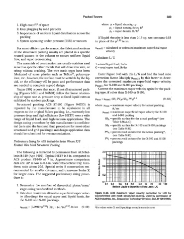
fabricated of some plastics such as Teflon@, polypropy- Enter Figure 9-48 with this L/G and find the load ratio
lene, etc.; however, the surface must be wettable by the liq- correction factor. Multiply p,d by this factor to deter-
uid, or the efficiency will be poor, and performance data mine the corrected maximum superficial vapor velocity,
are needed to complete a good design. baXl, for X-100 and $100 packings.
h'utter [99] reports that most, if not all structured pack- Correct the maximum vapor velocity again for the pack-
ing (Figures 9-6LL and 96MM) foIlow the linear relation- ing type, if other than X-100 or S100.
ship of vapor rate vs. pressure drop at fixed liquid rates as
exhibited by random packings. ~lmax = pmaxl (SS1 WA/SSA w1)0.5 (9-63)
Structured packing ACS ST-100 (Figure 9-6DD) is where pmax = maximum vapor velocity for actual packing,
reported by the manufacturer to be equivalent in all ft/sec
respects to the original Sulzer packing, Le., extremely low p-1 = maximum superficial vapor velocity for X-100
pressure drop and high efficiency (low HETP) over a wide and SlOO packing
range of liquid load, and high-vacuum applications. The SSA = specific surface for the actual packing* (see
design rating procedure by this manufacturer is confiden- Table 9-36A-C)
tial (as is also the best and final procedure for most other SS1 = specific surface for X-100 and SlOO packings
(see Table 9-36)
structured and grid packings) and design application data WA = percent void volume for the actual packing*,
should be submitted for recommendations.
(see Table 9-36)
W1 = percent void volume for the X-100 and SlOO
Preliminary Sizing fw ACS Industries Series Woven X/S packings
Knitted Wire Mesh Structured Packing
The following is extracted by permission from ACS Bul-
letin B129 (Apr. 1992). Typical HETP is 3 in. compared to
ACS product ST-100 of 7 in. Approximate comparison
data are: AP as low as 0.1-in. water/theoretical tray; turn-
down ratio about 20:l. Special series S construction rec-
ommended for smaller columns, and transverse Series X
for larger ones. The suggested preliminary sizing proce-
dure is:
1. Determine the number of theoretical plates/trays/ Ratio of Liquid to Vapor Mass Flow Loads, L/G
stages using standardized methods.
2. Calculate minimum allowable superficial vapor veloc- Fiiun? 9-48. ACS maximum vapor velocity correction for UG for
ity (flooding) for equal vapor and liquid loads, for wovenntnitted wire mesh structured packing. Used by permission of
the X-100 and SlOO packings. ACS Industries, Inc., Separation Technology Division, Bull. 6-129 (1 992).
-
urnax1~ [0.0942/p0.33] [ (p~ ft/sec (9-62) *For other series X and S packings consult manufacturer.
=