
Page 115 - Applied Process Design for Chemical and Petrochemical Plants Volume I
P. 115
102 Applied Process Design for Chemical and Petrochemical Plants
Friction Drop for Flow of Vapors, Gases, and Steam q'h = rate of flow, cu ft/hr at standard conditions (14.7
Figure 2-30 psia and 60"F), SCFH.
A. The Darcy rational relation for compressible $ow [3] is: 1. When calculated AP total < 10 percent inlet pres-
sure, use p orv based on inlet or outlet conditions.
0.000336 f W'V 2. When calculated AP total > 10 percent inlet pres-
AP / 100 ft = (2-77)
d5 sure, but < 40 percent, use average p orV based on
0.000001959f (q ) S ' inlet and outlet conditions.
or, AP / 100 ft = (2-78) 3. When calculated AP total, PI to P, is > 40% of inlet
d5p pressure, primarily for long lines, use the following
choices, or break the line into segments and calcu-
The general procedures outlined previously for han-
dling fluids involving the friction factor, f, and the k late AP for each as above.
chart are used with the above relations. This is applicable
to compressible flow systems under the following condi- Also use Babcock formula given in another paragraph
tions [3]. for steam flow.
where S, = specific gravity of gas relative to air = the ratio of q'h = 24,700 [Yd2/S,] (AP pl/K)'12, CFH @ 14.7 psia
molecular weight of the gas to that of air. and 60°F (2-79)
AP,, W
1600
APf100 ft. = 0.000 336 f Wz/dsp P V tl .4 i
loOa
.5
600
.6
40 I 8w
500
30 Inc 2 .7 100
.8
.04 .9 d 300
1.0
30 7 200
r 40
E50
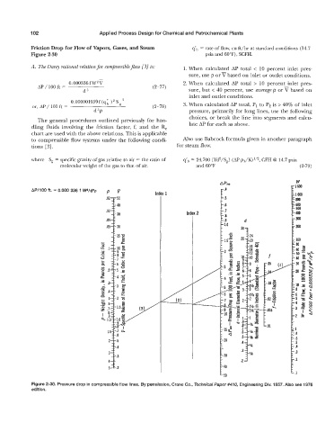
Figure 2-30. Pressure drop in compressible flow lines. By permission, Crane Co., Technical Paper #474 Engineering Div. 1957. Also see 1976
edition.