
Page 17 - Applied Process Design for Chemical and Petrochemical Plants Volume I
P. 17
Process Planning, Scheduling and Flowsheet Design 7
%ornotics 120psial Fuel Gas (20 psia) z
Ca us t i c t Synthesis Gas (435 psia) t(3:IHe:k)
-
- t 1 Nitrogen
-P
Vents
From
Air Plant
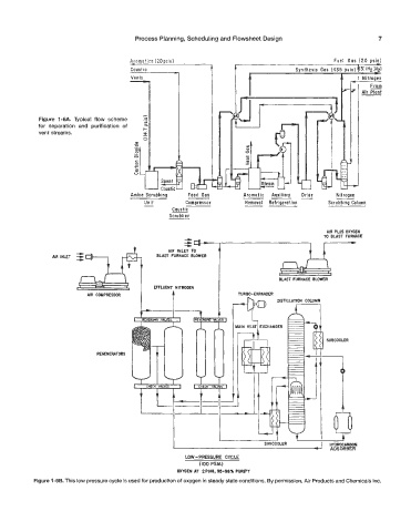
Figure 1-6A. Typical flow scheme .%
for separation and purification of
vent streams.
.-
0
U
x
._
0
a
c
0
2
0
0
- Feed Gas --- RI itrogen
Aromatic
Drier
Auxiliary
Amine Scrubbing
Unit Compressor Removal Refrigeration Scrubbing Column
-
Caustic
___
~
~~
Scrubber
AIR PLUS OXYGEN
z z TO BLAST FURNACE
I-'
AIR INLET TO t
BLAST FURNACE BLOWER
BLPST FURNACE BLOWER
EFFLUENT NITROGEN
AIR COMPRESSOR TURBO-EXPANDER
DISTILLATION COLUMN
A7
c '?
MAIN HEAT EXCHANGER
REGENERATORS
II
L-lt I k
I I
SUBCOOLER - HYDROCARBON
ADSORBER
4
LOW - PRESSURE CYCLE
(100 PSIA)
OXYGEN AT 2PSIG,95-98% PURITY
Figure 1-6B. This Bow pressure cycle is used for production of oxygen in steady state conditions. By permission, Air Products and Chemicals Inc.