
Page 27 - Applied Process Design for Chemical and Petrochemical Plants Volume I
P. 27
Process Planning, Scheduling and Flowsheet Design 15
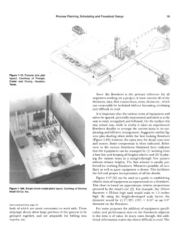
Figure 1-15. Pictorial plot plan
layout. Courtesy of Prengle,
Dukler’ and Crump, Houston,
Texas.
Since the flowsheet is the primary reference for all
engineers working on a project, it must contain all of the
decisions, data, flow connections, vents, drains etc., which
can reasonably be included without becoming confusing
and difficult to read.
It is important that the various items of equipment and
valves be spaced, pictorially represented and sized as to be
easy to read, recognized and followed. On the surface this
may sound easy, while in reality it takes an experienced
flowsheet detailer to arrange the various items in an eye-
pleasing and efficient arrangement. Suggestive outline fig-
ures plus shading often yields the best looking flowsheet
(Figure 1-10); however, the extra time for detail costs time
and money. Some compromise is often indicated. Refer-
ence to the various flowsheets illustrated here indicates
that the equipment can be arranged by (1) working from
a base line and keeping all heights relative and (2) by plac-
ing the various items in a straight-through flow pattern
without relative heights. The first scheme is usually pre-
ferred for working flowsheets. Whenever possible, all aux-
iliary as well as spare equipment is shown. This facilitates
the full and proper interpretation of all the details.
Figure 1-17 [2] can be used as a guide in establishing
relative sizes of equipment as represented on a flowsheet.
This chart is based on approximate relative proportions
Figure 1-16A Simple block model plant layout. Courtesy Of Socony piccured by the mind’s eye [2]. For example, the 10-foot
Mobil Oil Co. Inc. diameter x 33-foot high tank would scale to 1.5 inches
high. By using the height-developed scale factor, the
diameter would be (1.5”/33’) (10’) = 0.45” or say 0.5”
diameter on the flowsheet.
(text continued from page 11)
both of which are more convenient to work with. These For some purposes the addition of equipment specifi-
strip-type sheets allow large portions of the process to be cation and performance data on the flowsheets adjacent
grouped together, and are adaptable for folding into to the item is of value. In many cases though, this addi-
reports, etc. tional information makes the sheets difficult to read. The