Page 30 - Applied Process Design for Chemical and Petrochemical Plants Volume I
P. 30

18                       Applied  Process Design for Chemical and Petrochemical Plants

                                                               Materials of Construction for Lines

                                                                  The process designer must also consider the corrosive
                                                               nature of the fluids involved when selecting construction
                                                               materials for the various process and utility service lines.
                                                               Some designers attach these materials designations to the
                                                               line designation  on the flowsheets, while others identify
                                                               them on the Line Summary Table (Figure 1-24D). Some
                                                               typical pipe materials designations are:

                                                                                     CS40 -Carbon  steel, Sch. 40
                                                                                     CS80 -Carbon  steel, Sch. 80
                                                                                 SS316/10 -Stainless  steel
                                                                                             316m Sch. 10
                                                                                   GL/BE - Glass bevel ends
                                                                                      N40 -Nickel,  Sch. 40
                                                                                   TL/CS  - Teflon-lined carbon
                                                                                             steel
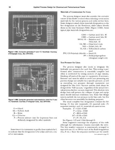
         Figure l-lw Computer generated I? and i D. flowsheet. Courtesy
         of lntergraph Corp., Bul. DPOl6AO.                       PVC/CS Polyvinyl chloride - lined CS
                                                                                       PP - Solid polypropylene
                                                                                             (designate weight sch)

                                                               Test Pressure for Lines
                                                                  The  process  designer  also  needs  to  designate  the
                                                               hydraulic test pressures for each line. This testing is per-
                                                               formed  after  construction  is  essentially  complete  and
                                                               often  is  conducted  by  testing  sections of  pipe  systems,
                                                               blanking off parts of the pipe or equipment, if necessary.
                                                               Extreme care must be taken to avoid over pressuring any
                                                               portion of pipe not suitable for a specific pressure, as well
                                                               as  extending  test  pressure  through  equipment  not
                                                               designed  for  that level. Vacuum  systems must always be
                                                               designed for “full vacuum,” regardless of the actual inter-
                                                               nal process absolute vacuum expected. This absolute zero
                                                               design basis will  prevent  the collapse of pipe and equip-
                                                               ment should internal conditions vary. Some line design
                                                               systems include the test pressure in the line code, but this
         Figure 1-186. Computer generated instrumentation detail for F!  and   often becomes too unwieldly for drafting purposes.
         I  D. flowsheet. Courtesy of lntegraph Corp., Bul. DPOl6AO.   The usual complete line designation contains the fol-
                                                               lowing:  (1) line  size  (nominal);  (2)  material  code;  (3)
                                                               sequence number; and (4) materials of construction.
               G - Glycol                                         Examples:  2”-CL&CS40
              SA-  Sulfuric Acid                                            3”-CL6a-CS40
               B  - Brine                                                   4”-RWl-CS40
              CL - Chlorine                                                16”-S150-CS40
               P-Process   mixture  (use for in-process lines not           3”-P-TL/   CS
                   definitely designated by other symbols)        See Figures 1-23 and 1-24 through D.
                                                                  Some engineers rearrange  the  sequence of  the  code
                                                               although  the  information  remains  essentially the  same.
                                                               The line number  sequence is  conveniently arranged  to
            Sometimes it is convenient to prefix these symbols by L   start with one (1) or 100 for each of the fluid designations
          to indicate that the designation is for a line and not a ves-   (CL, P, etc.) . Since the sequence numbers are for coordi-
         sel or instrument.                                                                       (text continued on page 23)
   25   26   27   28   29   30   31   32   33   34   35