
Page 318 - Applied Process Design for Chemical and Petrochemical Plants Volume I
P. 318
Mixing of Liquids 289
I Blending lpro@ler
Paddle L
I ITank Vol. 1 - 1,000,000 Gols.1
j Key= --_ 1
-- Batch Process
--
Continuous Process
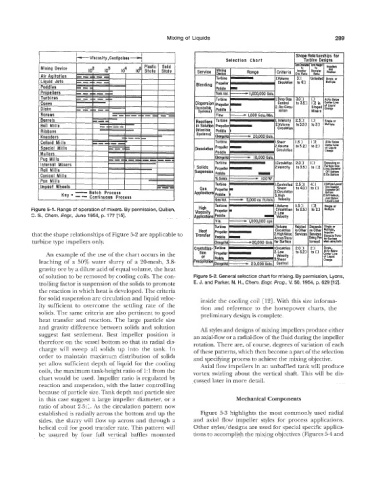
Figure 5-1. Range of operation of mixers. By permission, Quillen,
C. S., Chem. Engp., June 6954, p. 177 1151.
that the shape relationships of Figure 5-2 are applicable to
turbine type impelllers only.
An example of the use of thle chart occurs in the
leaching of a 50% water slurry of a 20-mesh, 3.8-
gravity ore by a dilute acid of equal volume, the heat
of solution to be removed by cooling coils. The con- Figure 5-2. General selection chart for mixing. y permission, Lyons,
trolling factor k suspension of the solids to promote E. J. and Parker, N. H., Chem. Engr. Prog., K 50,1954, p. 529 [I 21.
the reaction in which heat is developed. The criteria
for solid suspension are circulation and liquid veloc- inside the cooling coil [12]. With this size informa-
ity sufficient to overcome the settling rate of the ti~n and reference to the horsepower charts, the
solids. The same criteria are also pertinent to good preliminary design is complete.
heat transfer and reaction. The large particle size
and gravity (difference between solids and solution All styles and designs of mixing impellers
suggest fast settlement. Best impeller position is an axial-flow or a radial-flow of the fluid during the impeller
therefore on the vessel bottom so that its radial dis- rotation. There are, of course, degrees of variation of each
charge will sweep all solids up into the tank. In of these patterns, which then become a part of the selection
order to maintain maximum distribution of solids and speclfylng process to achieve the mixing objective.
yet allow su-Cficient depth of liquid for the cooling Axial flow impellers in an unbaffled tank will produce
coils, the maximum tank-height ratio of 1:l from the vortex swirling about the vertical shaft. Tinis will be dis-
chart would be used. Impeller ratio is regulated by cussed later in more detail.
reaction and suspension, with the latter controlling
because of particle size, Tank depth and particle size
in this case suggest a large impeller diameter, or a Mechanical Co
ratio of aibout 2 5:B. As the circulation pattern now
established is saldiaUy across the bottom and up the Figure 5-3 highlights the most commonly used radial
sides, the slurry will flow up across and through a and axial flow impeller styles for process applications.
helical coil for good transfer rate. This pattern will Other styles/designs are used for special specific applica-
be assured by four €dl vertical baffles mounted tions to accomplish the mixing objectives (Figures 5-4 and