
Page 41 - Applied Process Design for Chemical and Petrochemical Plants Volume I
P. 41
Process Planning, Scheduling and Flowsheet Design 29
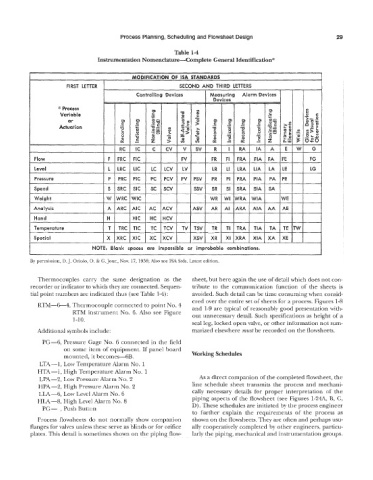
Table 1-4
Instrumentation Nomenclature-Complete General Identification*
MODIFICATION OF ISA STANDARDS
FIRST LETTER
Controlling Devices Measuring Alarm
Devices
I I
* Process
Variable
or
Actuation
IA
-
FIA
I Level LIA
PV PIA
?k?iY? ~ XIA
TV TIA
XI
XRA
XR
XSV
__
I NOTE: Blank spaces are impossible or improbable combinations.
By permission, D.J. Oriolo, 0. & G. Jour., Nov. 17, 1958; Also see ISA Stds. Latest edition.
Thermocouples carry the same designation as the sheet, but here again the use of detail which does not con-
recorder or indicator to which they are connected. Sequen- tribute to the communication function of the sheets is
tial point numbers are indicated thus (see Table 1-4) : avoided. Such detail can be time consuming when consid-
ered over the entire set of sheets for a process. Figures 1-8
RTM-6-4, Thermocouple connected to point No. 4 and 1-9 are typical of reasonably good presentation with-
RTM instrument No. 6. Also see Figure out unnecessary detail. Such specifications as height of a
1-10.
seal leg, locked open valve, or other information not sum-
Additional symbols include: marized elsewhere must be recorded on the flowsheets.
PG--6, Pressure Gage No. 6 connected in the field
on some item of equipment. If panel board
mounted, it becomes-6B. Working Schedules
LTA-1, Low Temperature Alarm No. 1
HTA--1, High Temperature Allarm No. 1
LPA-2, Low Pressure Alarm No. 2 As a direct companion of the completed flowsheet, the
HPA--2, High Pressure Alarm No. 2 line schedule sheet transmits the process and mechani-
EM--6, Low Level Alarm No. 6 cally necessary details for proper interpretation of the
-8, High Level Marm No. 8 piping aspects of the flowsheet (see Figures 1-24A, B, C,
PC- , Push E1utton D) . These schedules are initiated by the process engineer
to further explain the requiremlents of the process as
Process flowshects do not normally show companion shown on the flowsheets. They are often and perhaps usu-
flanges for valves unless these serve as blinds or for orifice ally cooperatively completed by other engineers, particu-
plates. This detail is sometimes shown on the piping flow- larly the piping, mechanical and instrumentation groups.