
Page 91 - Applied Process Design for Chemical and Petrochemical Plants Volume I
P. 91
78 Applied Process Design for Chemical and Petrochemical Plants
Reynolds number and the friction factor for all conditions
of flow using the appropriate f and K values.
K = f (L/D) (2-25)
hf = K(v~ - ~2)'/2g (2-31)
and:
hf = (f L/D) (v2/2g), ft fluid for pipe (2-26)
hf = (K) (v2/2g), ft fluid for valves and fittings (2-27)
1TH J AP/lOO eq. ft* = 0.0668 (pv/d2) = 0.0273 pLQ/d4,
psi/lOO eq. ft (2-32)
-.-
0 I 2 3 4 5 6 7 8 9 IO AP = (AP/lOO) (Leq), psi (2-33)
3-
D
D *Equivalent feet of straight pipe; i.e., straight pipe plus
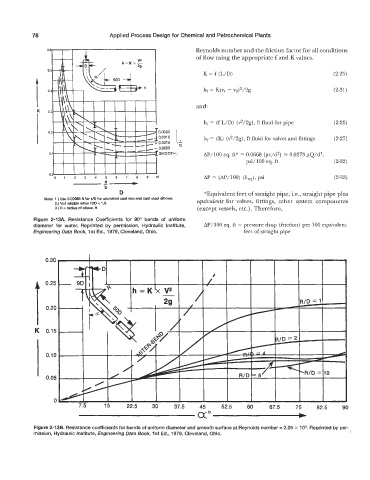
Note: 1 .) Use 0.00085 fi for FJD for uncoated cast iron and cast steel elbows.
2.) Not reliable when WD c 1 .O. equivalents for valves, fittings, other system components
3.) R = radius of elbow, fl (except vessels, etc.) . Therefore,
Figure 2-13A. Resistance Coefficients for 90" bends of uniform
diameter for water. Reprinted by permission, Hydraulic Institute, AP/lOO eq. ft = pressure drop (friction) per 100 equivalent
Engineering Data Book, 1 st Ed., 1979, Cleveland, Ohio. feet of straight pipe
Figure 2-13B. Resistance coefficients for bends of uniform diameter and smooth surface at Reynolds number = 2.25 x lo5. Reprinted by per-
mission, Hydraulic Institute, Engineering Data Book, 1st Ed., 1979, Cleveland, Ohio.