
Page 95 - Applied Process Design for Chemical and Petrochemical Plants Volume I
P. 95
82 Applied Process Design for Chemical and Petrochemical Plants
Nozzles and Orifices [3] p = ratio of small to large diameter orifices and noz-
zles and contractions or enlargements in pipes
These piping items shown in Figures 2-17 and 2-18 are
important pressure drop or head loss items in a system
and must be accounted for to obtain the total system pres- For discharging incompressible fluids to atmosphere,
sure loss. For liquids: take C values from Figures 2-17 or 2-18 if hL or AP is taken
as upstream head or gauge pressure.
q C’AJ2g(144)(AP)/p = C‘A[2ghL]1/2 (2-46)
For flow of compressible fluids use the net expansion
factor Y (see later discussion) [ 31 :
where q = cubic ft/sec of fluid at Jzowing conditions
C‘ = flow coefficient for nozzles and orifices
q = YC’A [2g (144) (AP)/P]~/~ (2-48)
C’ = C /dm, corrected for velocity of
approach (2-47)
where Y = net expansion factor for compressible flow
through orifices, nozzles, and pipe.
Note: C’ = C for Figures 2-17 and 2-18, corrected for velocity
of approach.
Cd = discharge coefficient for nozzles and orifices C‘ = flow coefficient from Figures 2-17 or 2-18. When
hL = differential static head or pressure loss across discharging to atmosphere, P = inlet gauge pres-
flange taps when C or C’ values come from Figures sure. (Also see critical flow discussion.)
2-17 and 2-18, ft of fluid. Taps are located one
diameter upstream and 0.5 diameter down from
the device. For estimating purposes in usual piping systems, the
A = cross section area of orifice, nozzle or pipe, sq ft values of pressure drop across an orifice or nozzle will
h = static head loss, ft of fluid flowing range from 2 to 5 psi. For more exact system pressure
AP = differential static loss, lbs/sq in. of fluid flowing, drop calculations, the loss across these devices should be
under conditions of hL above calculated using some size assumptions.
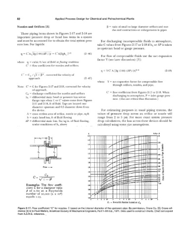
C
Flow 4
Cd
Example: The flow coeffi-
cient C for a diameter ratio
fi of 0.60 at a Reynolds
number of 20,000 (2 x 10⁴)
equals 1.03.
It, - Revnolds Number based on d,
Figure 2-17. Flow coefficient “C” for nozzles. C based on the internal diameter of the upstream pipe. By permission, Crane Co. [3]. Crane ref-
erence [Q] is to Fluid Meters, American Society of Mechanical Engineers, Part 1-6th Ed., 1971. Data used to construct charts. Chart not copied
from A.S.M.E. reference.