
Page 191 - 05. Subyek Teknik Mesin - Automobile Mechanical and Electrical Systems Automotive Technology Vehicle Maintenance and Repair (Vehicle Maintenance Repr Nv2) by Tom Denton
P. 191
2
Engine systems 175
Figure 2.190 Plastic inlet manifold
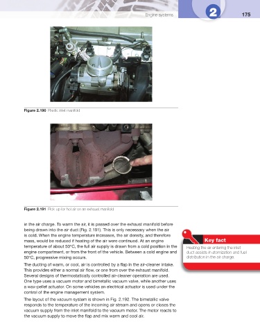
Figure 2.191 Pick-up for hot air on an exhaust manifold
in the air charge. To warm the air, it is passed over the exhaust manifold before
being drawn into the air duct ( Fig. 2.191 ). This is only necessary when the air
is cold. When the engine temperature increases, the air density, and therefore
mass, would be reduced if heating of the air were continued. At an engine Key fact
temperature of about 50°C, the full air supply is drawn from a cold position in the Heating the air entering the inlet
engine compartment, or from the front of the vehicle. Between a cold engine and duct assists in atomization and fuel
50°C, progressive mixing occurs. distribution in the air charge.
The ducting of warm, or cool, air is controlled by a fl ap in the air-cleaner intake.
This provides either a normal air fl ow, or one from over the exhaust manifold.
Several designs of thermostatically controlled air-cleaner operation are used.
One type uses a vacuum motor and bimetallic vacuum valve, while another uses
a wax-pellet actuator. On some vehicles an electrical actuator is used under the
control of the engine management system.
The layout of the vacuum system is shown in Fig. 2.192 . The bimetallic valve
responds to the temperature of the incoming air stream and opens or closes the
vacuum supply from the inlet manifold to the vacuum motor. The motor reacts to
the vacuum supply to move the fl ap and mix warm and cool air.