
Page 197 - 05. Subyek Teknik Mesin - Automobile Mechanical and Electrical Systems Automotive Technology Vehicle Maintenance and Repair (Vehicle Maintenance Repr Nv2) by Tom Denton
P. 197
2
Engine systems 181
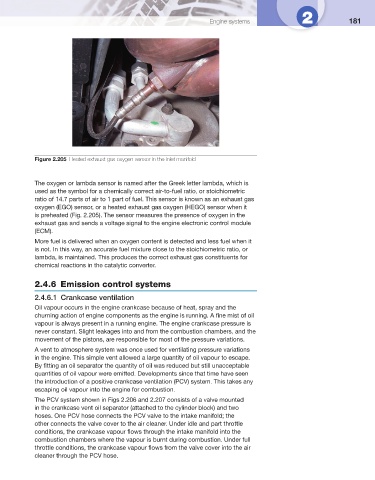
Figure 2.205 Heated exhaust gas oxygen sensor in the inlet manifold
The oxygen or lambda sensor is named after the Greek letter lambda, which is
used as the symbol for a chemically correct air-to-fuel ratio, or stoichiometric
ratio of 14.7 parts of air to 1 part of fuel. This sensor is known as an exhaust gas
oxygen (EGO) sensor, or a heated exhaust gas oxygen (HEGO) sensor when it
is preheated ( Fig. 2.205 ). The sensor measures the presence of oxygen in the
exhaust gas and sends a voltage signal to the engine electronic control module
(ECM).
More fuel is delivered when an oxygen content is detected and less fuel when it
is not. In this way, an accurate fuel mixture close to the stoichiometric ratio, or
lambda, is maintained. This produces the correct exhaust gas constituents for
chemical reactions in the catalytic converter.
2.4.6 Emission control systems
2.4.6.1 Crankcase ventilation
Oil vapour occurs in the engine crankcase because of heat, spray and the
churning action of engine components as the engine is running. A fi ne mist of oil
vapour is always present in a running engine. The engine crankcase pressure is
never constant. Slight leakages into and from the combustion chambers, and the
movement of the pistons, are responsible for most of the pressure variations.
A vent to atmosphere system was once used for ventilating pressure variations
in the engine. This simple vent allowed a large quantity of oil vapour to escape.
By fi tting an oil separator the quantity of oil was reduced but still unacceptable
quantities of oil vapour were emitted. Developments since that time have seen
the introduction of a positive crankcase ventilation (PCV) system. This takes any
escaping oil vapour into the engine for combustion.
The PCV system shown in Figs 2.206 and 2.207 consists of a valve mounted
in the crankcase vent oil separator (attached to the cylinder block) and two
hoses. One PCV hose connects the PCV valve to the intake manifold; the
other connects the valve cover to the air cleaner. Under idle and part throttle
conditions, the crankcase vapour fl ows through the intake manifold into the
combustion chambers where the vapour is burnt during combustion. Under full
throttle conditions, the crankcase vapour fl ows from the valve cover into the air
cleaner through the PCV hose.