
Page 201 - 05. Subyek Teknik Mesin - Automobile Mechanical and Electrical Systems Automotive Technology Vehicle Maintenance and Repair (Vehicle Maintenance Repr Nv2) by Tom Denton
P. 201
2
Engine systems 185
( Fig. 2.212 ). Superchargers are driven from the engine crankshaft. Turbocharging
(supercharging) of an engine is not strictly an emission control device but a
method by which an increase in power and fuel effi ciency can be obtained from a
smaller engine. At the same time, there are improvements in exhaust emissions.
Forced air induction has advantages over natural aspiration, because cylinder
charging is more consistent over the full engine speed range. This helps to give
high torque and power over a wider speed range, improved overall performance
and improved fuel consumption.
Exhaust turbochargers use waste energy in the exhaust gas fl ow for power.
This method of air boost charging is suitable for all types of engine. However,
applications on small petrol engines are usually found only on high-performance Key fact
vehicles. Exhaust turbochargers use waste
Turbocharging of small high-speed diesel engines, used in cars and light vans, is energy in the exhaust gas fl ow for
power.
now very popular. Diesel engine cylinder charging can be increased from about
60% for naturally aspirated engines to about 90% with exhaust turbocharging.
The increased volume of air means that a corresponding increase in fuel can
be delivered and more torque and power can be obtained per litre of engine
capacity. Turbochargers use the energy in the exhaust gas to drive a turbine. The
turbine is connected by means of a shaft to a compressor wheel in the engine
air intake tract. The greater the fl ow of exhaust gas, the greater the speed of the
turbine and compressor wheel and therefore the amount of additional charging.
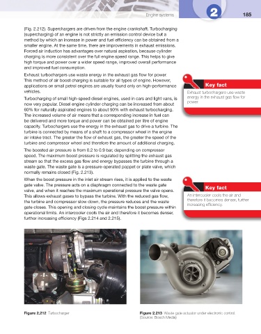
The boosted air pressure is from 0.2 to 0.9 bar, depending on compressor
speed. The maximum boost pressure is regulated by splitting the exhaust gas
stream so that the excess gas fl ow and energy bypasses the turbine through a
waste gate. The waste gate is a pressure-operated poppet or plate valve, which
normally remains closed ( Fig. 2.213 ).
When the boost pressure in the inlet air stream rises, it is applied to the waste
gate valve. The pressure acts on a diaphragm connected to the waste gate Key fact
valve, and when it reaches the maximum operational pressure the valve opens.
This allows exhaust gases to bypass the turbine. With the reduced gas fl ow, An intercooler cools the air and
the turbine and compressor slow down, the pressure reduces and the waste therefore it becomes denser, further
increasing effi ciency.
gate closes. This opening and closing cycle maintains the boost pressure within
operational limits. An intercooler cools the air and therefore it becomes denser,
further increasing effi ciency ( Figs 2.214 and 2.215 ).
Figure 2.212 Turbocharger Figure 2.213 Waste gate actuator under electronic control.
(Source: Bosch Media)