
Page 203 - 05. Subyek Teknik Mesin - Automobile Mechanical and Electrical Systems Automotive Technology Vehicle Maintenance and Repair (Vehicle Maintenance Repr Nv2) by Tom Denton
P. 203
2
Engine systems 187
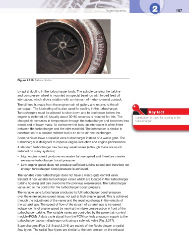
Figure 2.216 Turbine blades
by spiral ducting in the turbocharger body. The spindle carrying the turbine
and compressor wheel is mounted on special bearings with forced feed oil
lubrication, which allows rotation with a minimum of metal-to-metal contact.
The oil feed is made from the engine main oil gallery and returns to the oil
sump/pan. The lubricating oil is also used for cooling in the turbocharger.
Turbochargers must be allowed to slow down and to cool down before the Key fact
engine is switched off. Usually about 30–60 seconds is required for this. The Lubrication is used for cooling in the
charged air increases in temperature through the turbocharger and becomes less turbocharger.
dense and of lower mass. To overcome this loss, an intercooler is often fi tted
between the turbocharger and the inlet manifold. The intercooler is similar in
construction to a coolant radiator but is an air-to-air heat exchanger.
Some vehicles have a variable vane turbocharger instead of a waste gate. The
turbocharger is designed to improve engine induction and engine performance.
A standard turbocharger has two key weaknesses (although these are much
reduced on many systems):
High engine speed produces excessive turbine speed and therefore creates
●
excessive turbocharger boost pressure.
Low engine speed does not produce suffi cient turbine speed and therefore not
●
enough turbocharger boost pressure is achieved.
The variable vane turbocharger does not have a waste-gate control valve.
Instead, it has variable turbocharger vanes which are located in the turbocharger
turbine housing and can overcome the previous weaknesses. The turbocharger
vanes act as the control for the turbocharger boost pressure.
The variable vane turbocharger produces its full turbocharger boost pressure
over the entire engine speed range, not just at high engine speed. This is achieved
through the adjustment of the vanes and the resulting change in the velocity of
the exhaust gas. The speed of fl ow of the stream of exhaust gas is increased
independently of engine speed by varying the intake cross-section in front of the
turbocharger turbine. The variable vanes are controlled by the powertrain control
module (PCM). A duty cycle signal from the PCM controls a vacuum supply to the
turbocharger vacuum diaphragm unit using a solenoid valve ( Fig. 2.217 ).
Superchargers ( Figs 2.218 and 2.219 ) are mainly of the Roots blower or radial
fl ow types. The radial fl ow types are similar to the compressor on the exhaust