
Page 211 - 05. Subyek Teknik Mesin - Automobile Mechanical and Electrical Systems Automotive Technology Vehicle Maintenance and Repair (Vehicle Maintenance Repr Nv2) by Tom Denton
P. 211
2
Engine systems 195
Table 2.1 Stages of carburation
Stage Description Diagram
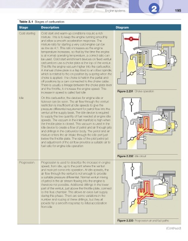
Cold starting Cold start and warm-up conditions require a rich
mixture. This is to keep the engine running smoothly
and allow a smooth acceleration response. The
mixture ratio for starting a very cold engine can be
as low as 4:1. This ratio increases as the engine
temperature increases, so that by the time the engine
is at normal operating temperature, a correct ratio can
be used. Cold start enrichment devices on fi xed venturi
carburettors use a choke plate at the top of the venturi.
This lifts the engine vacuum higher into the carburettor.
A manual choke plate is a fl ap fi tted to an offset spindle,
which is rotated to the on position by a spring when the
choke is applied. The choke is held in the partial and
off positions by a cam connected to the choke cable.
There is usually a linkage between the choke plate lever
and the throttle, to increase the engine speed. This
increase in speed is called fast idle Figure 2.231 Choke operation
Idle On this carburettor, the devices for engine idle or
tickover can be seen. The air fl ow through the venturi
restriction is insuffi cient at idle speeds to give the
pressure differential requirement for petrol fl ow into the
venturi at the supply beak. The idle device is required
to supply the low quantity of fuel needed at engine idle
speeds. The vacuum in the inlet manifold is high when
the throttle plate is closed. This vacuum is used in the
idle device to create a fl ow of petrol and air through jets
and drillings in the carburettor body. The petrol and air
mixture enters the air intake through the idle port just
below the throttle plate. The size of the pilot petrol jet
and adjustment of the air fl ow provides a suitable air to
fuel ratio for engine idle operation
Figure 2.232 Idle circuit
Progression Progression is used to describe the increase in engine
speed, from idle, up to the point where the venturi
and main jet come into operation. At idle speeds, the
air fl ow through the venturi is not enough to provide
a suitable pressure differential. Normal venturi mixing
of petrol in the air stream fl owing into the engine is
therefore not possible. Additional drillings in the lower
part of the venturi, just above the throttle plate, connect
to the fl oat chamber. This allows an extra fuel supply
during this phase. There are some variations in the
number and routing of these drillings, but they all
provide for a smooth response to initial acceleration
from idle
Figure 2.233 Progression air and fuel paths
(Continued)