
Page 212 - 05. Subyek Teknik Mesin - Automobile Mechanical and Electrical Systems Automotive Technology Vehicle Maintenance and Repair (Vehicle Maintenance Repr Nv2) by Tom Denton
P. 212
2
196 Automobile mechanical and electrical systems
Table 2.1 (Continued)
Stage Description Diagram
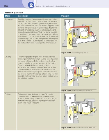
Acceleration If rapid acceleration is demanded, the vacuum in the
venturi is lost for an instant when the throttle is opened
quickly. The petrol fl ow through the supply beak from
the fl oat chamber cuts off and without a supplementary
supply a ‘fl at spot’ would be experienced. To prevent
fl at spots on acceleration, an accelerator pump and
petrol discharge nozzle are fi tted. The pump consists
of a piston or diaphragm, a one-way valve and drillings
for a petrol supply from the fl oat chamber. The pump is
connected by a rod or cam linkage to the throttle plate
lever. This causes a pulse of petrol to be sprayed into
the venturi when rapid opening of the throttle occurs
Figure 2.234 Accelerator pump and jet
Cruising The cruising speed range is wide and covers most
operating conditions from light cruising up to a position
just below full throttle. Petrol is drawn from the fl oat
chamber into the air stream passing into the engine.
The supply beak design and position give good
atomization and distribution of the fuel in the air fl ow.
The air fuel ratio in a simple venturi becomes richer
with an increase in engine speed. Correction devices
are used to maintain the correct ratio mixture. It is also
desirable for the engine to run on a lean mixture when
the vehicle is cruising
Figure 2.235 Emulsion tube in use at cruise
Full load Carburettors were designed to meet full throttle
conditions without additional devices being fi tted.
However, these designs were unable to meet tougher
environmental regulations, which required accurate
control of exhaust emissions
Figure 2.236 Emulsion tube and ‘beak’ at full load