
Page 220 - 05. Subyek Teknik Mesin - Automobile Mechanical and Electrical Systems Automotive Technology Vehicle Maintenance and Repair (Vehicle Maintenance Repr Nv2) by Tom Denton
P. 220
2
204 Automobile mechanical and electrical systems
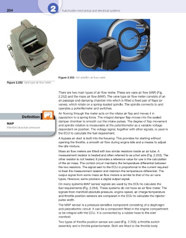
Figure 2.253 Hot wire/fi lm air fl ow meter
Figure 2.252 Vane type air fl ow meter
There are two main types of air fl ow meter. These are vane air fl ow (VAF) ( Fig.
2.252 ) and the mass air fl ow (MAF). The vane type air fl ow meter consists of an
air passage and damping chamber into which is fi tted a fi xed pair of fl aps (or
vanes), which rotate on a spring-loaded spindle. The spindle connects to and
operates a potentiometer and switches.
Air fl owing through the meter acts on the intake air fl ap and moves it in
Defi nition opposition to a spring force. The integral damper fl ap moves into the sealed
damper chamber to smooth out the intake pulses. The degree of fl ap movement
MAP
and spindle rotation is measurable at the potentiometer as a variable voltage
Manifold absolute pressure
dependent on position. The voltage signal, together with other signals, is used in
the ECU to calculate the fuel requirement.
A bypass air duct is built into the housing. This provides for starting without
opening the throttle, a smooth air fl ow during engine idle and a means to adjust
the idle mixture.
Mass air fl ow meters are fi tted with two similar resistors inside an air tube. A
measurement resistor is heated and often referred to as a hot wire ( Fig. 2.253 ). The
other resistor is not heated. It provides a reference value for use in the calculation
of the air mass. The control circuit maintains the temperature differential between
the two resistors. The signal sent to the ECU is proportional to the current required
to heat the measurement resistor and maintain the temperature differential. The
output signal from some mass air fl ow meters is similar to that of the air vane
types. However, some produce a digital output signal.
On many systems MAP sensor signals are used by the ECU to calculate the
fuel requirements ( Fig. 2.254 ). These systems do not have an air fl ow meter. The
signals from manifold absolute pressure, engine speed, air charge temperature
and throttle position sensors are compared in the ECU to calculate the injector
pulse width.
The MAP sensor is a pressure-sensitive component consisting of a diaphragm
and piezoelectric circuit. It can be a component fi tted in the engine compartment
or be integral with the ECU. It is connected by a rubber hose to the inlet
manifold.
Two types of throttle position sensor are used ( Fig. 2.255 ): a throttle switch
assembly and a throttle potentiometer. Both are fi tted to the throttle body