
Page 224 - 05. Subyek Teknik Mesin - Automobile Mechanical and Electrical Systems Automotive Technology Vehicle Maintenance and Repair (Vehicle Maintenance Repr Nv2) by Tom Denton
P. 224
2
208 Automobile mechanical and electrical systems
Figure 2.262 Solenoid air valve
Figure 2.263 Fuel supply components shown in red
connected to the valve in the air channel ( Fig. 2.262 ). All idle control valves
operate to hold the engine speed to the stored data specifi cation for engine
temperature and load conditions.
Stepper motors are also used to control idle speed and give graduated positions
depending on the supply current to a number of electric windings. Sensors in the
idle control mechanisms provide feedback signals to the ECU to provide data on
operation and position.
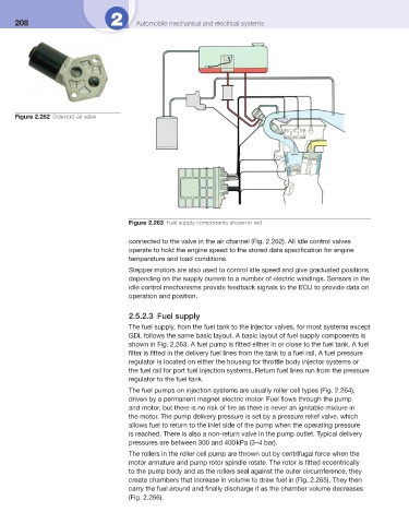
2.5.2.3 Fuel supply
The fuel supply, from the fuel tank to the injector valves, for most systems except
GDi, follows the same basic layout. A basic layout of fuel supply components is
shown in Fig. 2.263 . A fuel pump is fi tted either in or close to the fuel tank. A fuel
fi lter is fi tted in the delivery fuel lines from the tank to a fuel rail. A fuel pressure
regulator is located on either the housing for throttle body injector systems or
the fuel rail for port fuel injection systems. Return fuel lines run from the pressure
regulator to the fuel tank.
The fuel pumps on injection systems are usually roller cell types ( Fig. 2.264 ),
driven by a permanent magnet electric motor. Fuel fl ows through the pump
and motor, but there is no risk of fi re as there is never an ignitable mixture in
the motor. The pump delivery pressure is set by a pressure relief valve, which
allows fuel to return to the inlet side of the pump when the operating pressure
is reached. There is also a non-return valve in the pump outlet. Typical delivery
pressures are between 300 and 400 kPa (3–4 bar).
The rollers in the roller cell pump are thrown out by centrifugal force when the
motor armature and pump rotor spindle rotate. The rotor is fi tted eccentrically
to the pump body and as the rollers seal against the outer circumference, they
create chambers that increase in volume to draw fuel in ( Fig. 2.265 ). They then
carry the fuel around and fi nally discharge it as the chamber volume decreases
( Fig. 2.266 ).