
Page 227 - 05. Subyek Teknik Mesin - Automobile Mechanical and Electrical Systems Automotive Technology Vehicle Maintenance and Repair (Vehicle Maintenance Repr Nv2) by Tom Denton
P. 227
2
Engine systems 211
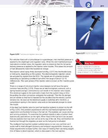
Figure 2.271 Injector operating
Figure 2.270 Fuel pressure regulator valve open
For vehicles fi tted with a turbocharger or supercharger, inlet manifold pressure is
applied to the diaphragm and regulator valve. When the inlet manifold pressure
Key fact
rises above a certain value, the regulator valve is closed so that the full pump
delivery pressure is applied to the injector valve nozzles. This raises the amount Injector signals are of a precise
of fuel delivered to match the boosted air charge. duration depending on operating
conditions but usually within the
The injector valves spray fi nely atomized fuel ( Fig. 2.271 ) into the throttle body range of about 1.5–10 milliseconds.
or inlet ports, depending on the system. The electromagnetic injection valves
are actuated by signals from the ECU. The signals are of a precise duration
depending on operating conditions but within the range of about 1.5–10.
milliseconds. This open phase of the injector valve is known as the ‘injector pulse
width’.
There is a range of individual injector valve designs but all have the same
common features ( Fig. 2.272 ). These are an electromagnetic solenoid, with a
spring-loaded plunger, connected to a jet needle in the injector valve nozzle.
The electrical supply to the solenoid is made from the system relay or ECU.
Grounding the other connection energizes the solenoid. This lifts the plunger
and jet needle so that fuel is injected for the duration that the electric current
remains live. As soon as the electrical supply is switched off in the ECU, a
compression spring in the injector valve acts on the solenoid plunger to close
the nozzle.
A top-feed fuel injector valve for port fuel injection systems is shown on the left
of Fig. 2.272 . One problem experienced with this fuel feed arrangement is fuel
vaporization and bubbles forming in the fuel rail. The bubbles can cause starting
and running problems. To overcome this problem lateral or side or bottom-feed
injectors are used (shown on the right). When fi tted in the fuel rail it can be seen
that any bubbles that may form will be at the top of the rail. They will therefore be
fl ushed out through the regulator as soon as the fuel pump is actuated.
The multipoint fuel injection system outlined above is now very common as it
works well to meet stringent economy and emission requirements. However, as
these requirements increase further, new ways of meeting them are being sought.
One of these is direct injection, which is discussed in the next section.