
Page 232 - 05. Subyek Teknik Mesin - Automobile Mechanical and Electrical Systems Automotive Technology Vehicle Maintenance and Repair (Vehicle Maintenance Repr Nv2) by Tom Denton
P. 232
2
216 Automobile mechanical and electrical systems
Figure 2.280 Electronic control unit (ECU), rail and injectors. (Source: Bosch Media)
Lambda
sensor
NO catalytic
x
converter
Lambda sensor
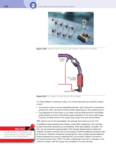
Figure 2.281 NO x catalytic converter. (Source: Bosch Media)
For these different operating modes, two central demands are raised for engine
control:
The injection point must be adjustable between ‘late’ (during the compression
●
phase) and ‘early’ (during the intake phase) depending on the operating point.
The adjustment for the drawn-in air mass must be detached from the throttle
●
pedal position to permit unthrottled engine operation in the lower load range.
However, throttle control in the upper load range must also be permitted.
With optimal use of the advantages, the average fuel saving is up to 15%.
In stratifi ed charge operation the nitrogen oxides (NO x ) segments in the very lean
exhaust cannot be reduced by a conventional, three-way catalytic converter. The
Key fact NO x can be reduced by approximately 70% through exhaust returns before the
In a GDi system, NO x emissions are catalytic converter. However, this is not enough to fulfi l the ambitious emission limits
reduced by an accumulator catalytic of the future. Therefore, emissions containing NO must undergo special treatment.
x
converter in the exhaust system. Engine designers are using an additional NO accumulator catalytic converter in
x
the exhaust system ( Fig. 2.281 ). The NO is deposited in the form of nitrates on the
x
converter surface, with the oxygen still contained in the lean exhaust.