
Page 240 - 05. Subyek Teknik Mesin - Automobile Mechanical and Electrical Systems Automotive Technology Vehicle Maintenance and Repair (Vehicle Maintenance Repr Nv2) by Tom Denton
P. 240
2
224 Automobile mechanical and electrical systems
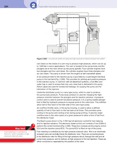
Figure 2.293 Low-pressure (white and grey) and high-pressure (in black) pressure fuel system
cam lobes on the inside of a cam ring to produce high pressure, which can be up
to 1400 bar in some applications. The cam is located in the pump body and the
plungers are in the rotor driven by the pump spindle. Four-cylinder engines have
two plungers and four cam lobes. Six-cylinder engines have three plungers and
six cam lobes. The pump is driven from the engine at half crankshaft speed.
A low-pressure feed to the injection pump is provided by a submerged electrical
pump in the fuel tank ( Fig. 2.293 ). This provides for priming and positive pressure
in the injection pump. In common with all diesel fuel systems, a fuel fi lter and
water trap is used to ensure that only very clean fuel is delivered to the pump.
Return pipes are used for excess fuel leakage, for purging the pump and for
lubrication of the injectors.
Inside the distributor pump is a vane type pump, which is used to produce
the pump body pressure. Pump body pressure is used for charging the high-
pressure chamber between the plungers and for injection advance. A pressure
control valve is used to prevent excessive pressure. It is a spring-loaded plunger
that is lifted by hydraulic pressure to expose ports in the valve bore. This will then
allow fuel to fl ow back to the inlet side of the vane-type pump.
An overfl ow throttle valve, in the pump housing, is used to allow a defi ned
quantity of fuel to fl ow back to the fuel tank at all times. This provides some
cooling in the pump and venting of air during pump priming. A second, larger
overfl ow bore in the valve opens at a given pressure to allow a fl ow of fuel from
the distributor head.
The Bosch pump shown in Fig. 2.294 has full electronic control for fuel metering
and for injection advance. The electronic diesel control unit consists of two ECMs to
perform the control functions ( Fig. 2.295 ). These two modules are the engine control
Key fact ECU and the injection pump ECU. The pump ECU is fi tted on top of the pump.
Fuel metering is controlled by Fuel metering is controlled by the high-pressure solenoid valve. This is an electrically
the ECU, which operates a high- actuated valve set centrally inside the distributor rotor. There are connecting bores
pressure solenoid valve. in the distributor rotor for fi lling of the high-pressure circuit, through the inlet port at
pump body pressure, and for delivery at high pressure to the fuel injectors. These are
either connected or separated by the position of the valve.