
Page 272 - 05. Subyek Teknik Mesin - Automobile Mechanical and Electrical Systems Automotive Technology Vehicle Maintenance and Repair (Vehicle Maintenance Repr Nv2) by Tom Denton
P. 272
2
256 Automobile mechanical and electrical systems
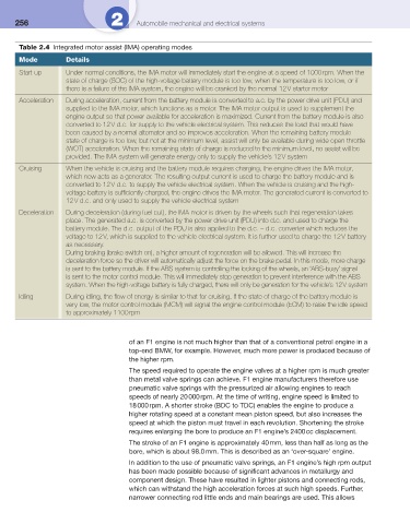
Table 2.4 Integrated motor assist (IMA) operating modes
Mode Details
Start-up Under normal conditions, the IMA motor will immediately start the engine at a speed of 1000 rpm. When the
state of charge (SOC) of the high-voltage battery module is too low, when the temperature is too low, or if
there is a failure of the IMA system, the engine will be cranked by the normal 12 V starter motor
Acceleration During acceleration, current from the battery module is converted to a.c. by the power drive unit (PDU) and
supplied to the IMA motor, which functions as a motor. The IMA motor output is used to supplement the
engine output so that power available for acceleration is maximized. Current from the battery module is also
converted to 12 V d.c. for supply to the vehicle electrical system. This reduces the load that would have
been caused by a normal alternator and so improves acceleration. When the remaining battery module
state of charge is too low, but not at the minimum level, assist will only be available during wide open throttle
(WOT) acceleration. When the remaining state of charge is reduced to the minimum level, no assist will be
provided. The IMA system will generate energy only to supply the vehicle’s 12 V system
Cruising When the vehicle is cruising and the battery module requires charging, the engine drives the IMA motor,
which now acts as a generator. The resulting output current is used to charge the battery module and is
converted to 12 V d.c. to supply the vehicle electrical system. When the vehicle is cruising and the high-
voltage battery is suffi ciently charged, the engine drives the IMA motor. The generated current is converted to
12 V d.c. and only used to supply the vehicle electrical system
Deceleration During deceleration (during fuel cut), the IMA motor is driven by the wheels such that regeneration takes
place. The generated a.c. is converted by the power drive unit (PDU) into d.c. and used to charge the
battery module. The d.c. output of the PDU is also applied to the d.c. – d.c. converter which reduces the
voltage to 12 V, which is supplied to the vehicle electrical system. It is further used to charge the 12 V battery
as necessary.
During braking (brake switch on), a higher amount of regeneration will be allowed. This will increase the
deceleration force so the driver will automatically adjust the force on the brake pedal. In this mode, more charge
is sent to the battery module. If the ABS system is controlling the locking of the wheels, an ‘ABS-busy’ signal
is sent to the motor control module. This will immediately stop generation to prevent interference with the ABS
system. When the high-voltage battery is fully charged, there will only be generation for the vehicle’s 12 V system
Idling During idling, the fl ow of energy is similar to that for cruising. If the state of charge of the battery module is
very low, the motor control module (MCM) will signal the engine control module (ECM) to raise the idle speed
to approximately 1100 rpm
of an F1 engine is not much higher than that of a conventional petrol engine in a
top-end BMW, for example. However, much more power is produced because of
the higher rpm.
The speed required to operate the engine valves at a higher rpm is much greater
than metal valve springs can achieve. F1 engine manufacturers therefore use
pneumatic valve springs with the pressurized air allowing engines to reach
speeds of nearly 20 000 rpm. At the time of writing, engine speed is limited to
18 000 rpm. A shorter stroke (BDC to TDC) enables the engine to produce a
higher rotating speed at a constant mean piston speed, but also increases the
speed at which the piston must travel in each revolution. Shortening the stroke
requires enlarging the bore to produce an F1 engine’s 2400 cc displacement.
The stroke of an F1 engine is approximately 40 mm, less than half as long as the
bore, which is about 98.0 mm. This is described as an ‘over-square’ engine.
In addition to the use of pneumatic valve springs, an F1 engine’s high rpm output
has been made possible because of signifi cant advances in metallurgy and
component design. These have resulted in lighter pistons and connecting rods,
which can withstand the high acceleration forces at such high speeds. Further,
narrower connecting rod little ends and main bearings are used. This allows