
Page 279 - 05. Subyek Teknik Mesin - Automobile Mechanical and Electrical Systems Automotive Technology Vehicle Maintenance and Repair (Vehicle Maintenance Repr Nv2) by Tom Denton
P. 279
3
Electrical systems 263
The amount of resistance offered by a conductor is determined by four factors
( Fig. 3.9 ):
Length – The greater the length the greater the resistance.
●
Cross-sectional area – The larger the area the smaller the resistance.
●
The material – The resistance offered by a conductor will vary according to the
●
material from which it is made.
Temperature – Most metals increase in resistance as temperature increases.
●
When resistors are connected so that there is only one path for the same
current to fl ow through each resistor they are connected in series. In a series
circuit ( Fig. 3.10 ):
Current is the same in all parts of the circuit.
●
Applied voltage equals the sum of the volt drops around the circuit.
●
The total resistance of the circuit equals the sum of the individual resistance
●
values.
When resistors are connected such that they provide more than one path for the
current to fl ow in, and have the same voltage across each component, they are
connected in parallel. In a parallel circuit ( Fig. 3.11 ):
Voltage across all components of a parallel circuit is the same.
●
Total current from the source is the sum of the current fl owing in each branch.
●
The current splits up depending on each component’s resistance.
The total resistance of the circuit is the sum of the reciprocal (one divided by
●
the resistance) values.
Magnetism can be created by a permanent magnet or by an electromagnet
( Fig. 3.12 ). The space around a magnet in which the magnetic effect can be
detected is called the magnetic fi eld. Flux lines or lines of force represent the
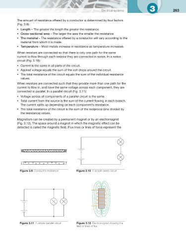
Figure 3.9 Conductor resistance Figure 3.10 A simple series circuit
Figure 3.11 A simple parallel circuit Figure 3.12 Electromagnet showing the
fi eld or lines of fl ux