
Page 284 - 05. Subyek Teknik Mesin - Automobile Mechanical and Electrical Systems Automotive Technology Vehicle Maintenance and Repair (Vehicle Maintenance Repr Nv2) by Tom Denton
P. 284
3
268 Automobile mechanical and electrical systems
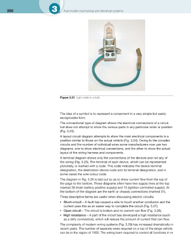
Figure 3.21 Light cable to a bulb
The idea of a symbol is to represent a component in a very simple but easily
recognizable form.
The conventional type of diagram shows the electrical connections of a circuit
but does not attempt to show the various parts in any particular order or position
( Fig. 3.23 ).
A layout circuit diagram attempts to show the main electrical components in a
position similar to those on the actual vehicle ( Fig. 3.24 ). Owing to the complex
circuits and the number of individual wires some manufacturers now use two
diagrams, one to show electrical connections, and the other to show the actual
layout of the wiring harness and components.
A terminal diagram shows only the connections of the devices and not any of
the wiring ( Fig. 3.25 ). The terminal of each device, which can be represented
pictorially, is marked with a code. This code indicates the device terminal
designation, the destination device code and its terminal designation, and in
some cases the wire colour code.
The diagram in Fig. 3.26 is laid out so as to show current fl ow from the top of
the page to the bottom. These diagrams often have two supply lines at the top
marked 30 (main battery positive supply) and 15 (ignition controlled supply). At
the bottom of the diagram are the earth or chassis connections (marked 31).
Three descriptive terms are useful when discussing electric circuits:
Short-circuit – A fault has caused a wire to touch another conductor and the
●
current uses this as an easier way to complete the circuit ( Fig. 3.27 ).
Open circuit – The circuit is broken and no current can fl ow ( Fig. 3.28 ).
●
High resistance – A part of the circuit has developed a high resistance (such
●
as a dirty connection), which will reduce the amount of current that can fl ow.
The complexity of modern wiring systems ( Fig. 3.29 ) has increased dramatically in
recent years. The number of separate wires required on a top of the range vehicle
can be in the region of 1500. The wiring loom required to control all functions in or