Page 289 - 05. Subyek Teknik Mesin - Automobile Mechanical and Electrical Systems Automotive Technology Vehicle Maintenance and Repair (Vehicle Maintenance Repr Nv2) by Tom Denton
P. 289

3
      272                                 Automobile mechanical and electrical systems


                                          Figure 3.29      Wiring harness


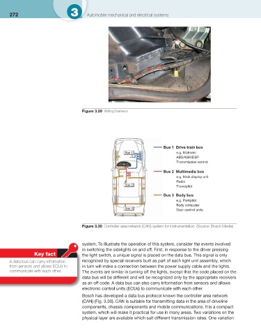
                                                                              Bus 1  Drive train bus
                                                            Bus 1                   e.g. Motronic
                                                                                    ABS/ASR/ESP
                                                                                    Transmission control

                                                                              Bus 2  Multimedia bus
                                                                                    e.g. Main display unit
                                                                                    Radio
                                                            Bus 2
                                                                                    Travelpilot
                                                                              Bus 3  Body bus
                                                                                    e.g. Parkpilot

                                                                                    Body computer
                                                            Bus 3
                                                                                    Door control units


                                          Figure 3.30      Controller area network (CAN) system for instrumentation.    (Source: Bosch Media)


                                        system. To illustrate the operation of this system, consider the events involved
                                        in switching the sidelights on and off. First, in response to the driver pressing
                               Key fact   the light switch, a unique signal is placed on the data bus. This signal is only
              A data bus can carry information   recognized by special receivers built as part of each light unit assembly, which
      from sensors and allows ECUs to   in turn will make a connection between the power supply cable and the lights.
      communicate with each other.      The events are similar in turning off the lights, except that the code placed on the
                                        data bus will be different and will be recognized only by the appropriate receivers
                                        as an off code. A data bus can also carry information from sensors and allows
                                        electronic control units (ECUs) to communicate with each other.
                                          Bosch has developed a data bus protocol known the controller area network
                                        (CAN) ( Fig. 3.30   ). CAN is suitable for transmitting data in the area of driveline
                                        components, chassis components and mobile communications. It is a compact
                                        system, which will make it practical for use in many areas. Two variations on the
                                        physical layer are available which suit different transmission rates. One variation
   284   285   286   287   288   289   290   291   292   293   294