
Page 315 - 05. Subyek Teknik Mesin - Automobile Mechanical and Electrical Systems Automotive Technology Vehicle Maintenance and Repair (Vehicle Maintenance Repr Nv2) by Tom Denton
P. 315
3
298 Automobile mechanical and electrical systems
+
+
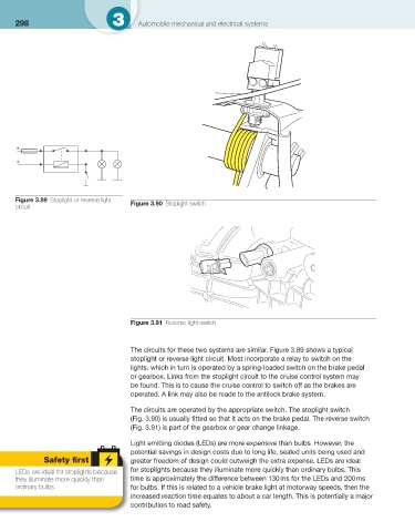
Figure 3.89 Stoplight or reverse light Figure 3.90 Stoplight switch
circuit
Figure 3.91 Reverse light switch
The circuits for these two systems are similar. Figure 3.89 shows a typical
stoplight or reverse light circuit. Most incorporate a relay to switch on the
lights, which in turn is operated by a spring-loaded switch on the brake pedal
or gearbox. Links from the stoplight circuit to the cruise control system may
be found. This is to cause the cruise control to switch off as the brakes are
operated. A link may also be made to the antilock brake system.
The circuits are operated by the appropriate switch. The stoplight switch
( Fig. 3.90 ) is usually fi tted so that it acts on the brake pedal. The reverse switch
( Fig. 3.91 ) is part of the gearbox or gear change linkage.
Light emitting diodes (LEDs) are more expensive than bulbs. However, the
potential savings in design costs due to long life, sealed units being used and
Safety fi rst greater freedom of design could outweigh the extra expense. LEDs are ideal
LEDs are ideal for stoplights because for stoplights because they illuminate more quickly than ordinary bulbs. This
they illuminate more quickly than time is approximately the difference between 130 ms for the LEDs and 200 ms
ordinary bulbs. for bulbs. If this is related to a vehicle brake light at motorway speeds, then the
increased reaction time equates to about a car length. This is potentially a major
contribution to road safety.