
Page 196 - Automotive Engineering Powertrain Chassis System and Vehicle Body
P. 196
CH AP TER 7 .1 Hybrid vehicle design
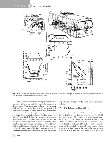
Fig. 7.1-19 Daimler-Benz OE 303 hybrid conversions: (a) diesel/electric hybrid package; (b) flywheel drive hybrid; (c) characteristics of
flywheel hybrid; (d) flywheel losses; (e) diesel losses.
During acceleration the mechanical gear stage is auto- drive wheels, compared with those for a conventional
matically shifted as the vari-drive hydraulic transmission vehicle.
changes speed. This results in the almost constant slope
(full line) in the curves shown at (c) compared with 7.1.5.3 Advanced hybrid bus
aconventionalbus(dottedline).Initiallytheflywheelalone
is used, then the diesel is brought in during deceleration, as A joint venture between MAN and Voith has resulted
seen in the bottom half of the figure. Flywheel power P s is in the NL 202 DE low floor concept city bus, Fig. 7.1-20,
260 kW immediately before the constant-power cruising designed to carry 98 passengers at a maximum speed
phase, during which the diesel drives. During deceleration of 70 kph, (a). No steps are involved at any of the
the flywheel is recharged and its power is 200 kW, corre- entrances which lead directly to a completely level
sponding diesel power being shown by P d . Flywheel energy deck height of between 317 and 340 mm. The rear-
content and losses are seen at (d); the inertia losses are mounted horizontally positioned diesel engine allows
replaced by diesel energy. The diesel losses are seen at (e) fitment of a bench seat at the rear of the bus; it drives
together with the transmission losses between engine and a generator with only electrical connection to the Voith
198