
Page 249 - Automotive Engineering Powertrain Chassis System and Vehicle Body
P. 249
Types of suspension and drive CHAPTER 8.1
Fig. 8.1-80 Front cross-section view of the engine; and drive axle of a standard four-wheel-drive vehicle (BMW assembly diagram).
The basic vehicle has rear-wheel drive and, in order to also be able to drive the front wheels, the front axle power take-off 4 had to be
moved into the space of the oil pan. The intermediate shaft 1 bridges the distance to the right inner CV joint and thus ensures
drive shafts of equal length to both wheels (items 2 and 3 and Fig. 8.1-51). Part 1 is mounted on one side in the non-lockable
differential 4 and on the other side in the outrigger 5. This, and the casing 6, are screwed to the oil pan.
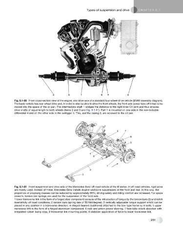
Fig. 8.1-81 Front suspension and drive axle of the Mercedes-Benz off-road vehicle of the M series. In off-road vehicles, rigid axles
are mostly used. Instead of these, Mercedes-Benz installs double wishbone suspensions at the front and rear. In this way, the
proportion of unsprung masses can be reduced by approximately 66%; driving safety and riding comfort are increased. For space
reasons, torsion-bar springs are used for the suspension of the front axle.
1 lower transverse link in the form of a forged steel component because of the introduction of torque by the torsion bars (2) and notch
insensitivity off road conditions; 2 torsion bars (spring rate of 50 Nm/degree); 3 vertically adjustable torque support which can be
placed in any position in a transverse direction; 4 integral bearers (subframe) attached to the box-type frame by 4 bolts; 5 upper
transverse link in the form of a forged aluminium component; 6 rack and pinion power steering, 7 twin-tube shock absorber with
integrated rubber bump stop, 8 transverse link mounting points; 9 stabilizer application of force to lower transverse link.
251