
Page 769 - Automotive Engineering Powertrain Chassis System and Vehicle Body
P. 769
CHAP TER 2 2. 1 Exterior noise: Assessment and control
Fig. 22.1-44 Measuring tyre noise using an Austrian trailer: after Sandberg (1998).
Sound pressure measured alongside a rolling tyre Appendix 22.1A : Valve and port
mounted on a special trailer. Various trailers are
described in Sandberg (1998). One example, taken geometry
from Sandberg (1998) is sketched in Fig. 22.1-44.
Measuring tyre noise on a rolling road rig in the labo- At low valve lifts, the open area of the valve is given by
ratory (Pope and Reynolds, 1976; Sandberg and (Heywood, 1988)
Ejsmont, 1993).
L v
A m ¼ pL v cos bðD v 2w þ sin 2bÞ (A22.1.1)
2
22.1.4.4 Controlling airborne tyre noise w
for > L v > 0
by design sin bcos b
Some tyre design guidance has emerged for reducing At intermediate valve lift,
airborne tyre noise: 2 2 1=2
A m ¼ pD m ½ðL v w tan bÞ þ w (A22.1.2)
Reduce the tread modulus (Muthukrishnan, 1990). " ! # 1=2
2
D D 2 w
Use a softer rubber on the tread to reduce the impact for p s w 2 þ w tan b L v >
of the block at the leading edge of the contact patch 4D m sin bcos b
(Jennewein and Bergmann, 1985).
Avoiding tension in the tread blocks to decrease tan- where D p is the port diameter.
gential vibration at the trailing edge of the contact When the valve lift is sufficiently large, the minimum
patch (Jennewein and Bergmann, 1985). flow area actually becomes the port area minus the valve
Avoid transverse grooves (Jennewein and Bergmann, stem area
1985) to reduce the effect of acoustic cavity reso-
nances. Short grooves with one end open are p
2
2
preferred. A m ¼ 4 ðD D Þ (A22.1.3)
p
s
Provide frequency the modulation in the tyre by " 2 2 ! #
selectively arranging tread elements of various sizes – for L v > D D s w 2 þ w tan b
p
so-called pitch sequencing (Williams, 1995). 4D m
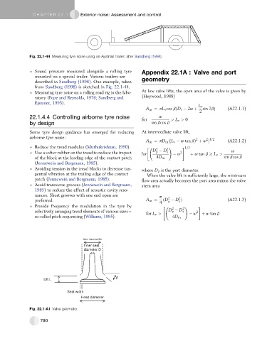
Stem diameter Ds
Inner seat
diameter D
Lift L
Seat width
Head diameter
Fig. 22.1-A1 Valve geometry.
780