
Page 764 - Automotive Engineering Powertrain Chassis System and Vehicle Body
P. 764
Exterior noise: Assessment and control C HAPTER 22.1
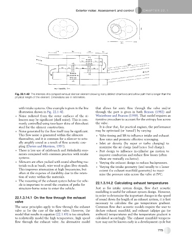
Fig. 22.1-42 The internals of a compact exhaust silencer element showing many distinct chambers and a flow path that is longer than the
physical length of the element. Dimensions are in millimetres.
with intake systems. One example is given in the line that allows for sonic flow through the valve and/or
illustration shown in Fig. 22.1-42. through the port is given in both Benson (1982) and
Noise radiated from the outer surfaces of the si- Winterbone and Pearson (1999). That model requires an
lencers may be significant (shell noise). This is com- iterative procedure to account for the entropy loss across
monly controlled using two-layer skins of thin-sheet the valve.
steel for the silencer construction. It is clear that, for practical engines, the performance
Noise generated by the flow itself may be significant. may be optimised (or ‘tuned’) by varying:
This flow noise is generated within the silencers Valve timing and lift to influence intake and exhaust
themselves, and it is common for a silencer to actu- flow rates and promote effective scavenging.
ally amplify sound as a result of flow acoustic cou- Inlet air density (by super or turbo charging) to
pling (Davies and Harrison, 1997). maximise the air charge (and hence fuel charge).
There is less use of sidebranch and Helmholtz reso- Port design to influence in-cylinder gas motion to
nators compared with common practice with intake improve combustion and reduce flow losses (often
systems. these are mutually exclusive).
Silencers are often packed with sound-absorbing ma- Varying the exhaust design to reduce backpressure.
terials such as basalt, wire wool or glass fibre strands. Varying the intake geometry (and usually to a lesser
This improves attenuation at high frequencies, but extent the exhaust manifold geometry) to maxi-
often at the expense of durability due to the reten- mise the pressure ratio across the valve at IVC.
tion of water within the materials.
The mounting of the exhaust system below the vehi-
cle is important to avoid the creation of paths for 22.1.3.14.2 Calculating exhaust temperatures
structure-borne noise to enter the vehicle. Just as for intake system design, flow duct acoustic
modelling is useful for exhaust system design. However,
in order to determine the important changes in the speed
22.1.3.14.1 On the flow through the exhaust
of sound down the length of an exhaust system, it is first
valve
necessary to calculate the gas temperature gradient.
The same principles apply to flow through the exhaust Common flow duct acoustic models require the user to
valve as for the case of the inlet valve. However, the declare exhaust manifold, and exhaust tailpipe gas (or
model that results in equation (22.1.49) is too simplistic ambient) temperatures and the temperature gradient is
to realistically model the high temperature, high speed calculated accordingly. The exhaust manifold tempera-
flow through the exhaust valve. An alternative model ture may not be known early in a development cycle but
775