
Page 761 - Automotive Engineering Powertrain Chassis System and Vehicle Body
P. 761
CHAP TER 2 2. 1 Exterior noise: Assessment and control
Flow
Flow
Fig. 22.1-36 The sidebranch resonator.
intake valves. Therefore, in the absence of cylinder-to-
cylinder overlap in intake valve opening, at any given time
only one valve will be open and the remainder of the
Fig. 22.1-34 The Helmholtz resonator.
branches act as sidebranch resonators to the branch with
22.1.3.13.4 Sidebranch resonators the open valve. This results in a strong peak in the at-
tenuation spectrum that is related to the primary runner
A simple 300-mm sidebranch resonator (illustrated in length.
Fig. 22.1-36) is fitted instead of the Helmholtz resonator, Away from this strong peak, there are additional
with the effect shown in Fig. 22.1-37. Fig. 22.1-38 shows troughs in the attenuation caused by resonances of the
a photograph of a typical production example of this. The zip tube. The frequencies at which these troughs occur
frequencies at which the system attenuation is improved may be controlled by varying the length of the zip tube as
through the action of the sidebranches may be calculated shown in Fig. 22.1-40.
for the zero flow case from:
Fig. 22.1-41 shows a line illustration of an intake
system where the design has been optimised using linear
4xf
¼ n n ¼ 1; 3; 5; 7; 9; . (22.1.80) acoustic theory.
c
where x is the sidebranch length and f is the resonant 22.1.3.13.6 Intake system mounting
frequency. In practical cases, the attenuation shown in The mounting of the intake system must give effective
Fig. 22.1-37 would be limited to around 40 dB by the attenuation of:
effects of flow noise. transmitted engine vibration;
shell noise.
22.1.3.13.5 The effects of the manifold and the Care should be taken to avoid noise ‘breaking out’
zip tube through the walls of flexible hoses. If the filter box is
The effect of adding a simple manifold and a zip tube to mounted on the vehicle body, the mounting system must
the filter box is shown in Fig. 22.1-39. The primary be flexible enough to allow for engine movement. The
runner lengths of the manifold’s branches act as side- filter box should be fixed to a low-mobility piece of
branch resonators when they are terminated by closed bodywork. Filter box mounts should be sufficiently
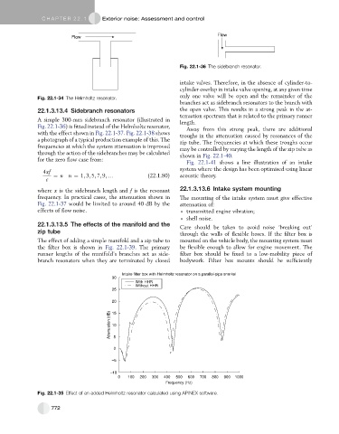
Intake filter box with Helmholtz resonator on a parallel-pipe snorkel
30
With HHR
Without HHR
25
20
Attenuation (dB) 10
15
5
0
–5
–10
0 100 200 300 400 500 600 700 800 900 1000
Frequency (Hz)
Fig. 22.1-35 Effect of an added Helmholtz resonator calculated using APINEX software.
772