
Page 758 - Automotive Engineering Powertrain Chassis System and Vehicle Body
P. 758
Exterior noise: Assessment and control C HAPTER 22.1
Wave decompositiontechniques (Daviesetal.,1999)– The peak attenuation will occur at frequencies away
Measure sound pressures at four known positions and from resonances in the snorkel and in the filter box.
solve the four simultaneous equations that result: These resonant frequencies can be estimated using the
equation below:
þ
þ
P 1 ¼ p e iðut b x 1 Þ þ p e iðutþb x 1 Þ (22.1.73) 2xf z nn ¼ 1; 2; 3; 4; . (22.1.78)
up
up
up
up
c
þ
þ
P 2 ¼ p e iðut b x 2 Þ þ p e iðutþb x 2 Þ (22.1.74) where
up
up
up
up
x
x
P 3 ¼ p þ e iðut b þ down 3 Þ þ p e iðutþb down 3 Þ x ¼ length
down down
(22.1.75) f ¼ frequency (Hz)
1
c ¼ speed of sound (m s )
x
x
P ¼ p þ e iðut b þ down 4 Þ þ p e iðutþb down 4 Þ The attenuation (predicted using a software known as
4
down
down
(22.1.76) APINEX) afforded by this simple intake system is shown
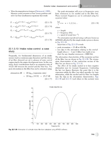
in Fig. 22.1-29.
Inspection of Fig. 22.1-29 reveals:
peak attenuation ¼ 25 dB at 650 Hz;
22.1.3.13 Intake noise control: a case two dips in the attenuation relating to the snorkel
study length when n ¼ 1 and 2 (filter box depth is too
short for any chamber resonances <1000 Hz).
Frequently, the fundamental dimensions of an intake
system (such as minimum pipe diameters and the choice The attenuation characteristics of the expansion portion
of air filter element) are set in advance of noise control of the filter box are shown in Fig. 22.1-30. The attenu-
engineering by the engine development team. In this case ation characteristics of the contraction section of the
study, those considerations lead to an expansion ratio of filter box are shown in Fig. 22.1-31.
18.33:1.00 between the snorkel and the filter box. The The effect of the intake snorkel is to have negative
peak attenuation in this filter box can be estimated using: attenuation near its resonant frequencies. Contrasting
the last two figures illustrates the point that it is the
attenuation dB ¼ 20 log 10 ðexpansion ratioÞ expansion within the filter box which provides the basic
attenuation, while the snorkel and the filter box lengths
¼ 20 log 10 ð18:33Þ¼ 25:27 dB tune the dips in the attenuation characteristics. Figs.
(22.1.77) 22.1-30 and 22.1-31 (and others in this section) were
Simple intake filter box
30
25
20
Attenuation (dB) 15
10
5
0
–5
–10
0 100 200 300 400 500 600 700 800 900 1000
Frequency (Hz)
Fig. 22.1-29 Attenuation of a simple intake filter box calculated using APINEX software.
769