
Page 755 - Automotive Engineering Powertrain Chassis System and Vehicle Body
P. 755
CHAP TER 2 2. 1 Exterior noise: Assessment and control
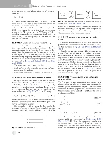
duct. It is assumed that below the first cut-off frequency P 1 u 1 P 2 u 2
given by: Acoustic Acoustic
source Element load
Ka ¼ 1:84 P + 1 P – 1 P + 2 P – 2
only plane waves propagate any great distance, while Fig. 22.1-26 The interaction between an acoustic source and an
other modes decay rapidly away from their source and acoustic load (Davies and Harrison, 1997).
are referred to as evanescent waves. interference between waves travelling in opposite di-
For vehicle systems the first cut-off frequency is in the rections. Traversing a microphone down the pipe will
2000þ Hz range, which for a four-stroke engine would show the standing wave pattern which may be viewed as
1
represent the 24th engine order at 5000 rev min .Itis the mode shape of a particular resonance.
therefore a reasonable and convenient simplification to
consider only plane wave propagation for vehicle intake 22.1.3.12.9 Acoustic sources and acoustic
and exhaust systems.
loads
22.1.3.12.7 Limits of linear acoustic theory The acoustic performance of a flow duct element de-
pends on the acoustic source and the acoustic load acting
Acoustic or linear theory remains appropriate as long as on it as illustrated in Fig. 22.1-26 (Davies and Harrison,
the waves travel along the uniform sections of duct be- 1997).
tween discontinuities without significant change in their Consider an exhaust system. The acoustic perfor-
shape. Typically, this is the case for pressure amplitudes mance of the first silencer will depend on the acoustic
in the region of 0.01–0.001 bar, with the limit falling load imposed on it. That load is the combined acoustic
with increasing frequency. Different investigations into impedance of the remainder of the exhaust system
the limits of the linear assumption in practical flow ducts downstream of the first silencer. Therefore, the acoustic
are reported in Davies and Holland (2004) and Payri performance of the first silencer depends on where in the
et al. (2000). system it is placed (hence a silencer that performs in
The plane wave restriction is useful as:
a certain way on the flow bench, may behave differently
it allows for a simpler means for including the effects on the vehicle). This is illustrated in Fig. 22.1-27 (Z is the
of flow into the analysis; acoustic impedance, the ratio of acoustic pressure to
it allows measurements to be made at duct walls. acoustic volume velocity).
22.1.3.12.8 Acoustic plane waves in ducts 22.1.3.12.10 The acoustics of an unflanged
pipe with flow
Standing waves occur as a result of the interference be-
tween waves travelling out of the source and waves The final acoustic termination in an intake system is at
reflected by each discontinuity in area or more generally the snorkel orifice. The final acoustic termination for the
each discontinuity in acoustic impedance. The concept of exhaust system is the exhaust tailpipe. The inflow of air
one forward-travelling wave and one backward-travelling or outflow of exhaust gas produces a final acoustic load on
wave is illustrated in Fig. 22.1-25. In the following, the system that is well understood and takes the form of
a reflection coefficient r:
þ
pðx; tÞ¼ p ðx; tÞþ p ðx; tÞ (22.1.59) p
r ¼ (22.1.60)
þ
the magnitudes of p and p remain effectively invariant p þ
between discontinuities, while the relative phase will Z 1 þ r
vary in an organised manner. r c ¼ 1 r (22.1.62)
However, p(x, t) will vary along the duct due to the 0
presence of standing waves. These so-called standing and
waves do not actually stand at all but are the result of the
r ¼ Re iq ¼ Re i2kl (22.1.62)
where R is the modulus, q is the phase, k the wave-
p + number and l is an end correction (Davies et al., 1980;
Davies, 1987). Ideally, on the assumption that the pres-
p – sure waves remain plane, r / 1, R / 1and q /p .In
reality, the plane wave assumption remains realistic only
Fig. 22.1-25 Sound field in a duct. when the dimension a (pipe radius) remains a small
766