
Page 751 - Automotive Engineering Powertrain Chassis System and Vehicle Body
P. 751
CHAP TER 2 2. 1 Exterior noise: Assessment and control
45 down the exhaust systems of running IC engines. This
seems the most promising way of separating engine-
Flow noise
40 Tailpipe resonances breathing noise from flow noise. Rather, simpler experi-
SPL (dB re 20 × 10 6 Pa) 35 et al., 1999; Sievewright, 2000) although the distinction
Chamber resonances
mental methods have been used elsewhere (Selemet
between primary and secondary noise sources is not
30
possible with these (Kunz and Garcia, 1995).
The narrow band noise spectra shown in Figs. 22.1-19
25
spectral content of both intake and exhaust noise. The
20 and 22.1-20 give an indication of the typical level and
tonal quality of the noise, arising from the cyclic operation
15 of the engine is obvious.
10
0 500 1000 1500 2000 2500 3000 3500 4000 4500 5000
Frequency (Hz) 22.1.3.12 Flow duct acoustics
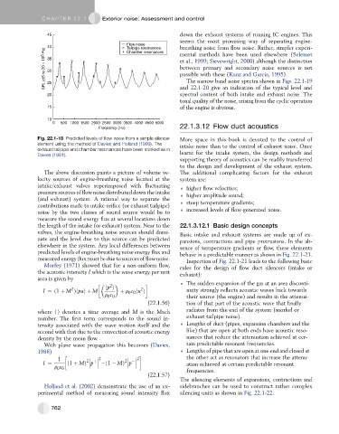
Fig. 22.1-18 Predicted levels of flow noise from a simple silencer More space in this book is devoted to the control of
element using the method of Davies and Holland (1999). The intake noise than to the control of exhaust noise. Once
exhaust tailpipe and chamber resonances have been marked as in
Davies (1981). learnt for the intake system, the design methods and
supporting theory of acoustics can be readily transferred
to the design and development of the exhaust system.
The above discussion paints a picture of volume ve- The additional complicating factors for the exhaust
locity sources of engine-breathing noise located at the system are:
intake/exhaust valves superimposed with fluctuating higher flow velocities;
pressure sources of flow noise distributed down the intake higher amplitude sound;
(and exhaust) system. A rational way to separate the
contributions made to intake orifice (or exhaust tailpipe) steep temperature gradients;
noise by the two classes of sound source would be to increased levels of flow-generated noise.
measure the sound energy flux at several locations down
the length of the intake (or exhaust) system. Near to the 22.1.3.12.1 Basic design concepts
valves, the engine-breathing noise sources should domi- Basic intake and exhaust systems are made up of ex-
nate and the level due to this source can be predicted pansions, contractions and pipe protrusions. In the ab-
elsewhere in the system. Any local differences between sence of temperature gradients or flow, these elements
predicted levels of engine-breathing noise energy flux and behave in a predictable manner as shown in Fig. 22.1-21.
measured energy flux must be due to sources of flow noise. Inspection of Fig. 22.1-21 leads to the following basic
Morfey (1971) showed that for a non-uniform flow, rules for the design of flow duct silencers (intake or
the acoustic intensity I which is the wave energy per unit exhaust):
area is given by
2 The sudden expansion of the gas at an area disconti-
2
2
I ¼ð1 þ M Þhpuiþ M hp i þ r c 0 hu i nuity strongly reflects acoustic waves back towards
0
r c 0 their source (the engine) and results in the attenua-
0
(22.1.56) tion of that part of the acoustic wave that finally
where CD denotes a time average and M is the Mach radiates from the end of the system (snorkel or
number. The first term corresponds to the sound in- exhaust tailpipe noise).
tensity associated with the wave motion itself and the Lengths of duct (pipes, expansion chambers and the
second with that due to the convection of acoustic energy like) that are open at both ends have acoustic reso-
density by the mean flow. nances that reduce the attenuation achieved at cer-
With plane wave propagation this becomes (Davies, tain predictable resonant frequencies.
1988) Lengths of pipe that are open at one end and closed at
1 2 þ 2 2 2 the other act as resonators that increase the attenu-
I ¼ ð1 þ MÞ p ð1 MÞ p ation achieved at certain predictable resonant
r c 0 frequencies.
0
(22.1.57)
The silencing elements of expansions, contractions and
Holland et al. (2002) demonstrate the use of an ex- sidebranches can be used to construct rather complex
perimental method of measuring sound intensity flux silencing units as shown in Fig. 22.1-22.
762