
Page 754 - Automotive Engineering Powertrain Chassis System and Vehicle Body
P. 754
Exterior noise: Assessment and control C HAPTER 22.1
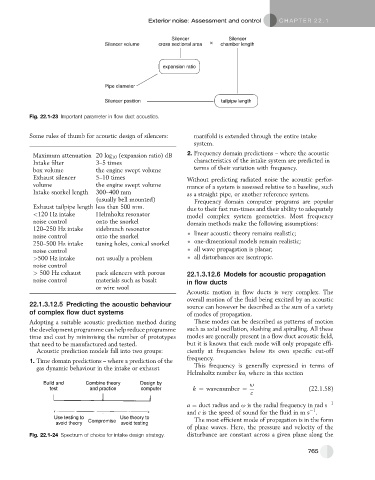
Silencer Silencer
Silencer volume cross sectional area × chamber length
expansion ratio
Pipe diameter
Silencer position tailpipe length
Fig. 22.1-23 Important parameter in flow duct acoustics.
Some rules of thumb for acoustic design of silencers: manifold is extended through the entire intake
system.
Maximum attenuation 20 log 10 (expansion ratio) dB 2. Frequency domain predictions – where the acoustic
Intake filter 3–5 times characteristics of the intake system are predicted in
box volume the engine swept volume terms of their variation with frequency.
Exhaust silencer 5–10 times Without predicting radiated noise the acoustic perfor-
volume the engine swept volume mance of a system is assessed relative to a baseline, such
Intake snorkel length 300–400 mm as a straight pipe, or another reference system.
(usually bell mounted) Frequency domain computer programs are popular
Exhaust tailpipe length less than 500 mm. due to their fast run-times and their ability to adequately
<120 Hz intake Helmholtz resonator model complex system geometries. Most frequency
noise control onto the snorkel domain methods make the following assumptions:
120–250 Hz intake sidebranch resonator
noise control onto the snorkel linear acoustic theory remains realistic;
250–500 Hz intake tuning holes, conical snorkel one-dimensional models remain realistic;
noise control all wave propagation is planar;
>500 Hz intake not usually a problem all disturbances are isentropic.
noise control
> 500 Hz exhaust pack silencers with porous 22.1.3.12.6 Models for acoustic propagation
noise control materials such as basalt in flow ducts
or wire wool
Acoustic motion in flow ducts is very complex. The
overall motion of the fluid being excited by an acoustic
22.1.3.12.5 Predicting the acoustic behaviour source can however be described as the sum of a variety
of complex flow duct systems of modes of propagation.
Adopting a suitable acoustic prediction method during These modes can be described as patterns of motion
the development programme can help reduce programme such as axial oscillation, sloshing and spiralling. All these
time and cost by minimising the number of prototypes modes are generally present in a flow duct acoustic field,
that need to be manufactured and tested. but it is known that each mode will only propagate effi-
Acoustic prediction models fall into two groups: ciently at frequencies below its own specific cut-off
1. Time domain predictions – where a prediction of the frequency.
gas dynamic behaviour in the intake or exhaust This frequency is generally expressed in terms of
Helmholtz number ka, where in this section
Build and Combine theory Design by u
test and practice computer k ¼ wavenumber ¼ (22.1.58)
c
a ¼ duct radius and u is the radial frequency in rad s 1
1
and c is the speed of sound for the fluid in m s .
Use testing to Use theory to The most efficient mode of propagation is in the form
avoid theory Compromise avoid testing
of plane waves. Here, the pressure and velocity of the
Fig. 22.1-24 Spectrum of choice for intake design strategy. disturbance are constant across a given plane along the
765