
Page 750 - Automotive Engineering Powertrain Chassis System and Vehicle Body
P. 750
Exterior noise: Assessment and control C HAPTER 22.1
engine-breathing noise is associated most with volume
velocity (or mass flux) sources, whereas flow noise is
associated mostly with stresses at a boundary or aero-
M
dynamic forces or fluctuating pressures.
Davies (1996) presents two acoustic source/filter
models for use in flow duct acoustics: one for excitation
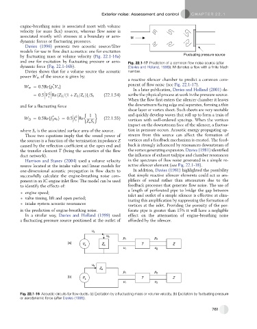
by fluctuating mass or volume velocity (Fig. 22.1-16a) Fluctuating pressure source
and one for excitation by fluctuating pressure or aero- Fig. 22.1-17 Prediction of a common flow noise source (after
dynamic force (Fig. 22.1-16b). (Davies and Holland, 1999)). M denotes a flow with a finite Mach
Davies shows that for a volume source the acoustic number.
power W m of the source is given by:
a reactive silencer chamber to predict a common com-
*
W m ¼ 0:5Refp V s g ponent of flow noise (see Fig. 22.1-17).
1
In a later publication, Davies and Holland (2001) de-
2
¼ 0:5 V RefZ 1 =ð1 þ Z 1 =Z e Þg=S s (22.1.54) scribe the physical process at work in the pressure source.
s
When the flow first enters the silencer chamber it leaves
and for a fluctuating force the downstream facing edge and separates, forming a thin
shear layer or vortex sheet. Such sheets are very unstable
1 and quickly develop waves that roll up to form a train of
2
*
W D ¼ 0:5Reff u s g¼ 0:5 f Re (22.1.55) vortices with well-ordered spacings. When the vortices
s
1
Z e S s
impact on the downstream face of the silencer, a fluctua-
where S s is the associated surface area of the source. tion in pressure occurs. Acoustic energy propagating up-
These two equations imply that the sound power of stream from this source can affect the formation of
the sources is a function of the termination impedance Z vortices and a feedback mechanism is created. The feed-
caused by the reflection coefficient at the open end and back is strongly influenced by resonances downstream of
the transfer element T (being the acoustics of the flow the vortex generating expansion. Davies (1981) identified
duct network). the influence of exhaust tailpipe and chamber resonances
Harrison and Stanev (2004) used a volume velocity in the spectrum of flow noise generated in a simple re-
source located at the intake valve and linear models for active silencer element (see Fig. 22.1-18).
one-dimensional acoustic propagation in flow ducts to In addition, Davies (1981) highlighted the possibility
successfully calculate the engine-breathing noise com- that simple reactive silencer elements could act as am-
ponent in an IC engine inlet flow. The model can be used plifiers of sound rather than attenuators due to the
to identify the effects of: feedback processes that generate flow noise. The use of
a length of perforated pipe to bridge the gap between
engine speed;
inlet and outlet of a simple silencer is effective at elim-
valve timing, lift and open period;
inating this amplification by suppressing the formation of
intake system acoustic resonances vortices at the inlet. Providing the porosity of the per-
in the prediction of engine-breathing noise. forate pipe is greater than 15% it will have a negligible
In a similar way, Davies and Holland (1999) used effect on the attenuation of engine-breathing noise
a fluctuating pressure source positioned at the outlet of afforded by the silencer.
u s
u e
p 1 p 2
(a) V s Z e T Z
u 1 u 2
u s
Z e
p 1 p 2
(b) P s T Z
u 1 u 2
Fig. 22.1-16 Acoustic circuits for flow ducts. (a) Excitation by a fluctuating mass or volume velocity, (b) Excitation by fluctuating pressure
or aerodynamic force (after Davies (1996)).
761