
Page 745 - Automotive Engineering Powertrain Chassis System and Vehicle Body
P. 745
CHAP TER 2 2. 1 Exterior noise: Assessment and control
The mean piston speed for this case is: In Fig. 22.1-12:
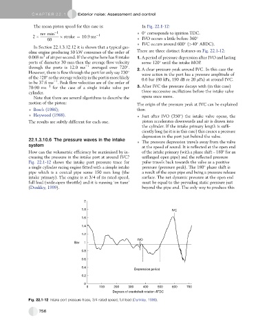
rev min 1 0 corresponds to ignition TDC.
2 stroke ¼ 10:9ms 1
60 IVO occurs a little before 360
IVC occurs around 600 (>40 ABDC).
In Section 22.1.3.12.12 it is shown that a typical gas-
oline engine producing 50 kW consumes of the order of There are three distinct features on Fig. 22.1-12:
3
0.068 m of air per second. If the engine here has 8 intake 1. A period of pressure depression after IVO and lasting
ports of diameter 30 mm then the average flow velocity some 120 until the intake MOP.
through the ports is 12.0 ms 1 averaged over 720 . 2. A clear pressure peak around IVC. In this case the
However, there is flow through the port for only say 230 wave action in the port has a pressure amplitude of
ofthe 720 so the averagevelocity inthe port ismore likely 0.6 bar (60 kPa, 190 dB re 20 mPa) at around IVC.
1
to be 37.6 ms . Peak flow velocities are of the order of
70-90 ms 1 for the case of a single intake valve per 3. After IVC the pressure decays with (in this case)
cylinder. three successive oscillations before the intake valve
Note that there are several algorithms to describe the opens once more.
motion of the piston: The origin of the pressure peak at IVC can be explained
Bosch (1986); thus:
Heywood (1988). Just after IVO (350 ) the intake valve opens, the
The results are subtly different for each one. piston accelerates downwards and air is drawn into
the cylinder. If the intake primary length is suffi-
ciently long (as it is in this case) this causes a pressure
depression in the port just behind the valve.
22.1.3.10.6 The pressure waves in the intake
The pressure depression travels away from the valve
system at the speed of sound. It is reflected at the open end
How can the volumetric efficiency be maximised by in- of the intake primary (with a phase shift – 180 for an
creasing the pressure in the intake port at around IVC? unflanged open pipe) and the reflected pressure
Fig. 22.1-12 shows the intake port pressure trace for pulse travels back towards the valve as a positive
a single cylinder racing engine fitted with a simple intake pressure (pressure peak). The 180 phase shift is
pipe which is a conical pipe some 150 mm long (the a result of the open pipe end being a pressure release
intake primary). The engine is at 3/4 of its rated speed, surface. The net dynamic pressure at the open end
full load (wide-open throttle) and it is running ‘on tune’ must be equal to the prevailing static pressure just
(Dunkley, 1999). beyond the pipe end. The only way to produce this
2
1.8 IVC
1.6
1.4
1.2
IVO
Bar 1
0.8
0.6
0.4
Depression period
0.2
0
0 100 200 300 400 500 600 700
Degrees of crankshaft rotation ATDC
Fig. 22.1-12 Intake port pressure trace, 3/4 rated speed, full load (Dunkley, 1999).
756