Page 741 - Automotive Engineering Powertrain Chassis System and Vehicle Body
P. 741

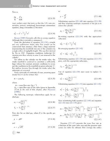
CHAP TER 2 2. 1       Exterior noise: Assessment and control


               Now as                                             so
                                                                        gP
                       2
                 vf   v u                                           r ¼  a 2                              (22.1.40)
                    ¼                                 (22.1.33)
                 vt   vxvt
                                                                  Substituting equation (22.1.40) into equation (22.1.36)
               most workers omit that term so that the 1-D, non-con-  and thus assuming isentropic expansion of the gas as it
               servative, inviscid, irrotational, homentropic momentum  enters the cylinder:
               equation, along a streamline (!) becomes:

                                                                                   1=g
                                                                         gp 01  p 2
                                                                    r ¼                                   (22.1.41)
                                                                     2
                          g   1  2                                        a 2  p 01
                       2
                  2
                 a ¼ a þ    2  u                      (22.1.34)            01
                  0
                                                                  Re-writing equation (22.1.34) with the appropriate
                 Benson (1982) famously calls this an energy equation  subscripts
               (although this is probably a misnomer).
                 From the derivation of equation (22.1.34) a simple  2     2  g   1  2
               and very well-known intake valve flow model can be    a 01  ¼ a þ  2  u 2                   (22.1.42)
                                                                           2
               constructed that assumes a flow from a large reservoir
               (representing the manifold) into one of the cylinders via  Re-arranging equation (22.1.42)
               a single orifice of negligible length. This was first derived
               by Tsu in 1947. Stagnation conditions (subscript 0,1  u ¼ða 2    a Þ  2                    (22.1.43)
                                                                                2
                                                                     2
               meaning zero flow velocity in zone 1) are assumed in the  2  01   2  g   1
               cylinder.
                 For inflow to the cylinder via the intake valve, the  Substituting equation (22.1.39) into equation (22.1.37)
               intake manifold is assumed to constitute a sufficiently  gives, with the appropriate subscripts,
               large volume for constant pressure conditions to occur,     2       g 1=g
               and the conditions in the manifold are given subscript ‘2’.  T 2 ¼  a 01  p 2              (22.1.44)
               For outflow (reverse flow through the intake valve) the      gR p 01
               subscripts are reversed.
                 From a principle of continuity of mass, assuming quasi  Use of equation (22.1.39) once more to replace T 2
                                                                  yields:
               steady flow it can be written that:
                                                                                  g 1=g
                                                                     2
                 _ m ¼ r u 2 A m                      (22.1.35)     a ¼ a 2 01  p 2                       (22.1.45)
                      2
                                                                     2
                                                                              p 01
               where                                              Substituting equation (22.1.45) into equation (22.1.43):
                                        1
                   _ m ¼ mass flow rate (kg s )
                 A m ¼ open flow area of the valve (given in Appendix                  p 2    g 1=g    2
                                                                     2
                 22.1A at the end of this chapter, after Heywood    u ¼    a 2 01    a 2 01
                                                                     2
                 [1988])                                                             p 01      g   1
                 The following isentropic relationships apply for an  2   2a 2 01    p 2  g 1=g
                                                                    u ¼        1                          (22.1.46)
                                                                     2
               ideal gas:                                                g   1      p 01

                         p 2  1=g                                 Now substituting both equation (22.1.46) and equation
                 r ¼ r 1                              (22.1.36)   (22.1.41) into (22.1.35) gives:
                  2
                         p 1


                          p 2  g 1=g                                              1=g 2a 2   1=2        g 1=g   1=2
                 T 2 ¼ T 1                            (22.1.37)         gp 01  p 2      01         p 2
                          p 1                                       _ m ¼  2                  1                A m
                                                                         a    p 01   g   1         p 01
                                                                          01
               Now also for an ideal gas, where R is the specific gas                2        2=g          g 1=g     1=2
               constant                                             _ m ¼  p 01 A m  2g  p 2    1    p 2
                                                                          a 01   g   1  p 01         p 01
                 p ¼ rRT                              (22.1.38)                                           (22.1.47)
               and                                                  Equation (22.1.47) presents the mass flow rate as
                     p ffiffiffiffiffiffiffiffiffiffi                                 a function of the open valve area and the pressure ratio
                 a ¼   gRT                            (22.1.39)   across the valve for subsonic flow through the orifice

                    752
   736   737   738   739   740   741   742   743   744   745   746