Page 738 - Automotive Engineering Powertrain Chassis System and Vehicle Body
P. 738
Exterior noise: Assessment and control     C HAPTER 22.1

                                                                                   3
           where                                                Note: If V d were in m then the resulting bmep would
             m f ¼ mass of fuel inducted per cycle (kg)       be in pascals.
             Now introducing the volumetric efficiency h v for the  The bmep is commonly used to assess the torque
           four-stroke engine only (where there is a distinct in-  output or load on an engine. If bmep is measured to be
           duction stroke) (Heywood, 1988)                    less than the known maximum bmep expected from an
                   2 _ m a                                    engine, then the engine must be operating at part load.
             h ¼                                   (22.1.8)
              v
                  r V N                                       bmep tends to zero at idle (h m tends to zero), with the
                   a;i
                      d
                                                              useful work produced during the cycle being used up in
           where                                              overcoming pumping losses (Heywood, 1988).
                                             3
             v d ¼ volume displaced by piston (m )              Note that:
                                      3
             r a,i ¼ inlet air density (kg m )
                                                                imep ¼ bmep þ fmep þ pmep þ amep      (22.1.15)
             The following equations are obtained for four-stroke  where
           engines (Heywood, 1988):
                                                                imep ¼ indicated mep (bar)
                  h h NV Q r ðF=AÞ
                   f v
                           hv a;i
                         d
             P I ¼                                 (22.1.9)     bmep ¼ brake mep (bar)
                           2                                    fmep ¼ rubbing friction mep (bar)
                  h h V Q r ðF=AÞ                               pmep ¼ pumping (or gas exchange) mep (bar)
                       d
                          hv a;i
                   f v
             T I ¼                                (22.1.10)
                         4p                                     amep ¼ accessory (alternator, pumps etc.) mep (bar)
             imep ¼ h h Q r ðF=AÞ                 (22.1.11)   So, to use Tim Drake’s criteria for excellent perfor-
                         hv a;i
                     f v
                                                              mance, the above equations show that the designer
             The mechanical efficiency h m allows the conversion of  needs:
           indicated power to brake power P b (the useful power as
           measured by a dynamometer)                           to maximise h v and r a,i in order to give good airflow;
                   P b      P f                                 to maximise h f and Q hv along with (F/A) whilst mini-
             h m  ¼   ¼ 1                         (22.1.12)     mising bsfc;
                  P ig      P ig
           where P ig is the gross indicated power (found from the     _ m f   1
           gross indicated work per cycle – the area under the PV  bsfc ¼  P  gJ  or g=kWh ðHeywood; 1988Þ
           diagram for compression and expansion strokes only)                                        (22.1.16)
           being the sum of brake power and friction power P f .
           Therefore,
             P ig ¼ P þ P f                       (22.1.13)   22.1.3.10.1 Some basic background terms
                   b
             Friction power includes the power used to overcome  Each cylinder of an engine with poppet valves (conven-
           friction in the engine (the rubbing friction) and in  tional four-stroke engines) will have the following
           pumping the gas in and out of the engine (the pumping  components:
           loss). Therefore, the mechanical efficiency is a function    Intake system, usually comprising a dirty-side
           of throttle setting and engine speed.                duct (or snorkel), supplying air to a filter (housed
             Brake mean effective pressure (bmep) is a useful mea-  in a filter box), which in turn supplies air to a manifold.
           sure of the torque output of an engine. It will be maximum    Intake manifold, distributing air (possibly air–fuel
           at the engine speed corresponding to peak torque     mixture) to each cylinder. Different configurations
           (Heywood, 1988) and will be 10–15% less at peak power.  of intake manifold exist, most are variants of end-
             Typical maximum bmep are (Heywood, 1988):          feed and centre-feed designs (Figs. 22.1-4 and 22.1-5
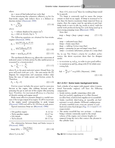
                                                                respectively).
              NA gasoline engine                  8–11 bar      The intake manifold has two sections – a plenum
              Turbo gasoline engine              12–17 bar      being a volume commonly equal to the swept
              NA diesels                          7–9 bar       volume of the engine, and primary lengths (or
              Turbo-diesels                      10–12 bar      runners) being the ducts that connect the plenum to
                                                                the cylinder head.
             The relationship between bmep and brake torque is
           (Heywood, 1988):
                         2pn r TðNmÞ
             bmep ðkPaÞ¼                          (22.1.14)
                             V d
                          3
           where V d is in dm .                               Fig. 22.1-4 End-feed intake manifold.

                                                                                                      749

