
Page 739 - Automotive Engineering Powertrain Chassis System and Vehicle Body
P. 739
CHAP TER 2 2. 1 Exterior noise: Assessment and control
known as the maximum opening point – MOP) at around
100–110 after top dead centre (ATDC) for the intake
valves and 110–120 after bottom dead centre (ABDC)
for the exhaust valves.
The period during which a valve is open (often called
the cam duration and measured in degrees of revolution
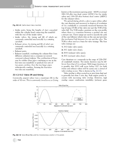
Fig. 22.1-5 Centre-feed intake manifold. of the crankshaft) is commonly measured between the
top of ramp (TOR) of the valve rise and the TOR of the
Intake ports, being the lengths of duct concealed valve fall. The TOR marks a position on the cam profile
within the cylinder head connecting the manifold where there is a transition between a gradual rise and
with the rear of the intake valves. a steeper rise. These ramps are used to smooth the path
Intake valves, the timing and lift of which are of the cam follower which rides on the cam and provides
commonly controlled mechanically by a rotating the mechanical link between the cam and the valve. The
camshaft. TOR is often used as a basis for valve timings. The four
Exhaust valves, the timing and lift of which are valve timings are:
commonly controlled mechanically by a rotating 1. IVO (inlet valve open);
camshaft. 2. IVC (inlet valve close);
Exhaust ports.
Exhaust manifold, combining the exhaust flow from 3. EVO (exhaust valve open);
different cylinders into a common (or several 4. EVC (exhaust valve close).
common) exhaust tailpipe. The combination of flows
Cam durations are commonly in the range of 220–250
may be sudden (four pipes combining as one in the
of crankshaft rotation. The intake duration may be dif-
four-into-one manifold) or gradual (two sets of
ferent from that of the exhaust. With longer durations, it
two pipes combine, then the two larger pipes
is possible that EVO will occur before IVC (so both
subsequently combine, forming the four-into-
intake and exhaust valves will be open) and a period of
two-into-one manifold).
valve overlap occurs. This is shown in Fig. 22.1-6.
Valve overlap is often quoted as an area (mm deg) and
22.1.3.10.2 Valve lift and timing is generally less than 5 mm deg. Peak engine power in-
Commonly, poppet valves have a maximum lift in the creases with increasing valve overlap. However, high
order of 10 mm. This is commonly timed to occur (being overlap causes combustion instability (exhaust gases
Valve lift profiles
10
8
Lift (mm) 6 4
Intake
2 Exhaust
0
0 100 200 300 400 500 600 700 800
Degrees of crankshaft revolution
Position of piston
0
Distance from TDC (m) –0.04
–0.02
–0.06
–0.08
–0.1
0 100 200 300 400 500 600 700 800
Degrees of crankshaft revolution
Fig. 22.1-6 Valve lift profiles and the instantaneous position of the piston.
750