
Page 78 - Automotive Engineering
P. 78
Emissions control CHAPTER 3.1
CO and HC. In so doing, they form hydrogen disulphide,
Table 3.1-3 Analyse, expressed in percentages, of particulates
which accounts for the unpleasant smell of the exhaust
from different types of diesel engine
when fuels with high sulphur content are burnt in an
Fuel- Oil- engine having an exhaust system equipped with a cata-
derived derived Insoluble Sulphates lytic converter.
Engine type HC HC ash D water An ingenious method of reducing visible particulates
emitted from a turbocharged engine in a bus has been
Ford 1.8 DI 15 13 70 2 investigated by MAN. Compressed air from the vehicle
braking system is injected in a controlled manner into the
Ford 1.8 IDI 48 20 30 2
combustion chambers to bum off the carbon. This in-
Average DI HD 14 7 25 4 creases the exhaust gas energy content, and therefore
turbocharged after- compensates for turbocharger performance falling off
cooled engine
under light load, including initially during acceleration
and while gear changes are being made.
Note: Horrocks (Ford Motor Co.) differentiated between the carbon and other
ash (at 41% and 13%, respectively), making the total 44%.
3.1.24 Particle traps
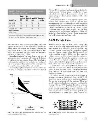
taken to reduce NO x increase particulates, the most Basically, particle traps are filters, mostly catalytically
appropriate solution is to use fuels of high quality, pri- coated to facilitate their regeneration (burning off of the
marily having low sulphur and aromatic contents and particles that have collected). Many of the filters are
high cetane number. The relationship between fuel extruded ceramic honeycomb type monoliths, though
quality and particulate and NO x output has been dem- some are foamed ceramic tubes. The honeycomb ce-
onstrated by Volvo (Fig. 3.1-24). ramic monoliths generally differ from those used for
A small proportion of the particulates is ash, most of catalytic conversion of the exhaust in gasoline engines, in
which comes from burning the lubricating oil. Reduction that the passages through the honeycomb section are
of sulphur in the fuel reduces the need for including, in sealed alternately along their lengths with ceramic plugs
lubricating oils, additives that neutralise the acid prod- (Fig. 3.1-25), so that the gas passes through their porous
ucts of combustion; these additives that are responsible walls. These walls may be less than 0.5 mm thick.
for a significant proportion of the ash content. Ceramic fibre wound on to perforated stainless steel
Incidentally, sulphur compounds can also reduce the tubes has also been used. These are sometimes termed
efficiency of catalytic converters for the oxidation of candle or deep bed-type filters. Their pores are larger
than those of the honeycomb type, and their wall
thicknesses greater.
If catalyst assisted, regeneration is done mostly at
temperatures around 600 C, and if not, at 900 C. Al-
ternatively, special catalysts may be used to lower further
the ignition temperature of the particles. These are
mostly platinum and palladium, which are useful also for
burning HCs and CO. Sulphate deposition adversely
affects the platinum catalyst, but the formation of sul-
phates is largely inhibited by palladium. Copper has been
used too, because it reduces the carbon particle igni-
tion temperature to about 350 C, but it suffers the
Fig. 3.1-24 Relationship between particulate emissions and fuel Fig. 3.1-25 Diagram showing how the gas flow is diverted in
quality, as established by Volvo. a particulate trap.
71