
Page 40 - Autonomous Mobile Robots
P. 40
Visual Guidance for Autonomous Vehicles 23
2D image 2D projection to ground plane
0 120
100 100
200 80
v (pixels) 300 Distance in front — Y(m) 60
400 40
20
500
0
0 200 400 600 –50 0 50
u (pixels) Vehicle X (m)
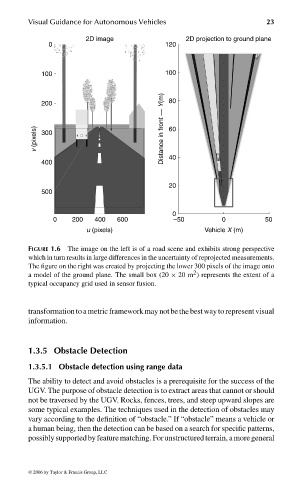
FIGURE 1.6 The image on the left is of a road scene and exhibits strong perspective
which in turn results in large differences in the uncertainty of reprojected measurements.
The figure on the right was created by projecting the lower 300 pixels of the image onto
2
a model of the ground plane. The small box (20 × 20 m ) represents the extent of a
typical occupancy grid used in sensor fusion.
transformation to a metric framework may notbe the best way to representvisual
information.
1.3.5 Obstacle Detection
1.3.5.1 Obstacle detection using range data
The ability to detect and avoid obstacles is a prerequisite for the success of the
UGV. The purpose of obstacle detection is to extract areas that cannot or should
not be traversed by the UGV. Rocks, fences, trees, and steep upward slopes are
some typical examples. The techniques used in the detection of obstacles may
vary according to the definition of “obstacle.” If “obstacle” means a vehicle or
a human being, then the detection can be based on a search for specific patterns,
possiblysupportedbyfeaturematching. Forunstructuredterrain, amoregeneral
© 2006 by Taylor & Francis Group, LLC
FRANKL: “dk6033_c001” — 2006/3/31 — 16:42 — page 23 — #23