
Page 63 - Autonomous Mobile Robots
P. 63
46 Autonomous Mobile Robots
Coupler
VCO
V
Antenna
Circulator
Linearizer
t
Anti
FFT aliasing High pass Low pass
filter filter filter
Mixer
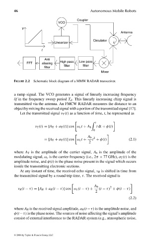
FIGURE 2.2 Schematic block diagram of a MMW RADAR transceiver.
a ramp signal. The VCO generates a signal of linearly increasing frequency
δf in the frequency sweep period T d . This linearly increasing chirp signal is
transmitted via the antenna. An FMCW RADAR measures the distance to an
object by mixing the received signal with a portion of the transmitted signal [17].
Let the transmitted signal v T (t) as a function of time, t, be represented as
t
v T (t) =[A T + a T (t)] cos ω c t + A b t dt + φ(t)
0
A b 2
=[A T + a T (t)] cos ω c t + t + φ(t) (2.1)
2
where A T is the amplitude of the carrier signal, A b is the amplitude of the
modulating signal, ω c is the carrier frequency (i.e., 2π × 77 GHz), a T (t) is the
amplitude noise, and φ(t) is the phase noise present in the signal which occurs
inside the transmitting electronic sections.
At any instant of time, the received echo signal, v R is shifted in time from
the transmitted signal by a round trip time, τ. The received signal is
A b 2
v R (t − τ) =[A R + a R (t − τ)] cos ω c (t − τ) + (t − τ) + φ(t − τ)
2
(2.2)
where A R is the received signal amplitude, a R (t −τ) is the amplitude noise, and
φ(t−τ) is the phase noise. The sources of noise affecting the signal’s amplitude
consist of external interference to the RADAR system (e.g., atmospheric noise,
© 2006 by Taylor & Francis Group, LLC
FRANKL: “dk6033_c002” — 2006/3/31 — 17:29 — page 46 — #6