
Page 95 - Autonomous Mobile Robots
P. 95
78 Autonomous Mobile Robots
(b) Trees
Wall
RADAR reflectors
30
20
Probability 0.5 0 10
1
0
–30
–20 Distance (m)
–10 –10
0
Clutter Distance (m) 10 –20
20
–30
30
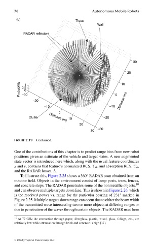
FIGURE 2.19 Continued.
One of the contributions of this chapter is to predict range bins from new robot
positions given an estimate of the vehicle and target states. A new augmented
state vector is introduced here which, along with the usual feature coordinates
x and y, contains that feature’s normalized RCS, ϒ R , and absorption RCS, ϒ a ,
and the RADAR losses, L.
To illustrate this, Figure 2.25 shows a 360 ◦ RADAR scan obtained from an
outdoor field. Objects in the environment consist of lamp-posts, trees, fences,
and concrete steps. The RADAR penetrates some of the nonmetallic objects, 10
and can observe multiple targets down line. This is shown in Figure 2.26, which
is the received power vs. range for the particular bearing of 231 marked in
◦
Figure 2.25. Multiple targets down range can occur due to either the beam width
of the transmitted wave intersecting two or more objects at differing ranges or
due to penetration of the waves through certain objects. The RADAR used here
10 At 77 GHz the attenuation through paper, fiberglass, plastic, wood, glass, foliage, etc., are
relatively low while attenuation through brick and concrete is high [37].
© 2006 by Taylor & Francis Group, LLC
FRANKL: “dk6033_c002” — 2006/3/31 — 17:29 — page 78 — #38