Page 310 - Autonomous Mobile Robots
P. 310

298                                    Autonomous Mobile Robots

                                          Y
                                                                   Leading vehicle


                                                                   P r
                                                                          P d


                                                               l     d
                                                               pg
                                                                  f
                                             Following vehicle
                                                          P f
                                                      P
                                           y           b
                                                  u
                                                                                   X
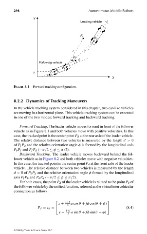
                                FIGURE 8.1 Forward tracking configuration.


                                8.2.2 Dynamics of Tracking Maneuvers
                                In the vehicle tracking system considered in this chapter, two car-like vehicles
                                are moving in a horizontal plane. This vehicle tracking system can be executed
                                in one of the two modes: forward tracking and backward tracking.

                                   Forward Tracking. The leader vehicle moves forward in front of the follower
                                vehicle as in Figure 8.1 and both vehicles move with positive velocities. In this
                                case, the tracked point is the center point P d at the rear axle of the leader vehicle.
                                The relative distance between two vehicles is measured by the length d > 0
                                of P f P d and the relative orientation angle φ is formed by the longitudinal axis
                                P b P f and P f P d (−π/2 ≤ φ ≤ π/2).
                                   Backward Tracking. The leader vehicle moves backward behind the fol-
                                lower vehicle as in Figure 8.2 and both vehicles move with negative velocities.
                                In this case, the tracked point is the center point P d at the front axle of the leader
                                vehicle. The relative distance between two vehicles is measured by the length
                                d > 0of P b P d and the relative orientation angle φ formed by the longitudinal
                                axis P f P b and P b P d (−π/2 ≤ φ ≤ π/2).
                                   For both cases, the point P d of the leader vehicle is related to the point P b of
                                the follower vehicle by the unified function, referred as the virtual intervehicular
                                connection as follows

                                                           1+f
                                                                                
                                                        x +   a cos θ + fd cos(θ + φ)
                                                            2
                                             P d = z d =                                 (8.4)
                                                           1+f
                                                        y +   a sin θ + fd sin(θ + φ)
                                                            2

                                 © 2006 by Taylor & Francis Group, LLC


                                 FRANKL: “dk6033_c008” — 2006/3/31 — 16:43 — page 298 — #4
   305   306   307   308   309   310   311   312   313   314   315