
Page 42 - Autonomous Mobile Robots
P. 42
Visual Guidance for Autonomous Vehicles 25
X
X = [x y z] T
x 1
e 1
x L Z
l 1
l 2 x R
x 2
O L e 2
e 1 O 2 B f
e 2
O R
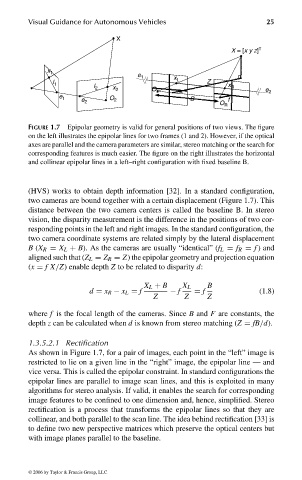
FIGURE 1.7 Epipolar geometry is valid for general positions of two views. The figure
on the left illustrates the epipolar lines for two frames (1 and 2). However, if the optical
axes are parallel and the camera parameters are similar, stereo matching or the search for
corresponding features is much easier. The figure on the right illustrates the horizontal
and collinear epipolar lines in a left–right configuration with fixed baseline B.
(HVS) works to obtain depth information [32]. In a standard configuration,
two cameras are bound together with a certain displacement (Figure 1.7). This
distance between the two camera centers is called the baseline B. In stereo
vision, the disparity measurement is the difference in the positions of two cor-
responding points in the left and right images. In the standard configuration, the
two camera coordinate systems are related simply by the lateral displacement
B (X R = X L + B). As the cameras are usually “identical” (f L = f R = f ) and
aligned such that (Z L = Z R = Z) the epipolar geometry and projection equation
(x = fX/Z) enable depth Z to be related to disparity d:
X L + B X L B
d = x R − x L = f − f = f (1.8)
Z Z Z
where f is the focal length of the cameras. Since B and F are constants, the
depth z can be calculated when d is known from stereo matching (Z = fB/d).
1.3.5.2.1 Rectification
As shown in Figure 1.7, for a pair of images, each point in the “left” image is
restricted to lie on a given line in the “right” image, the epipolar line — and
vice versa. This is called the epipolar constraint. In standard configurations the
epipolar lines are parallel to image scan lines, and this is exploited in many
algorithms for stereo analysis. If valid, it enables the search for corresponding
image features to be confined to one dimension and, hence, simplified. Stereo
rectification is a process that transforms the epipolar lines so that they are
collinear, and both parallel to the scan line. The idea behind rectification [33] is
to define two new perspective matrices which preserve the optical centers but
with image planes parallel to the baseline.
© 2006 by Taylor & Francis Group, LLC
FRANKL: “dk6033_c001” — 2006/3/31 — 16:42 — page 25 — #25