
Page 215 - Basic Structured Grid Generation
P. 215
204 Basic Structured Grid Generation
boundary edges between nodes will be sides. In other words, boundary integrity may
not be preserved, and further steps may be necessary.
The advancing front technique, first formulated by George (1971), is an unstructured
grid generation method which preserves boundary integrity and has the capacity to
create the clustering of high aspect-ratio triangles in boundary-layer regions. In this
method, outer and inner (if any) boundary curves of the computational domain, which
are commonly defined as piecewise-cubic splines based on a user-specified set of
points, are discretized by being divided into straight-line segments which correspond
to a chosen node distribution of the boundary of the domain. These sets of straight
edges compose the initial ‘fronts’. The fronts then move into the interior of the domain
in a ‘marching’ process, in which new points (nodes) and edges are created, old edges
are deleted, and triangular elements produced. The vertices of a new triangle consist of
the two nodes of a segment of a front and another node either already in the front or
newly created. This process continues until there are no edges left in the front, i.e. the
front has been annihilated, leaving behind a triangulated domain. Note that the initial
choice of nodes on the boundary curves must be strongly dependent on the required
grid-cell size, since edges in the initial front will be edges in the final triangulation.
8.3.2 Grid control
Any grid-generation method should provide for adequate grid control regarding accept-
able size and shape of grid cells. The main approach to control of grid-cell size in
the AFT (in two dimensions) throughout the computational domain involves first the
definition of certain required grid-cell characteristics, and then the generation of a
background grid. Control over these characteristics is obtained by the specification of
a spatial distribution of appropriate grid parameters over the background grid.
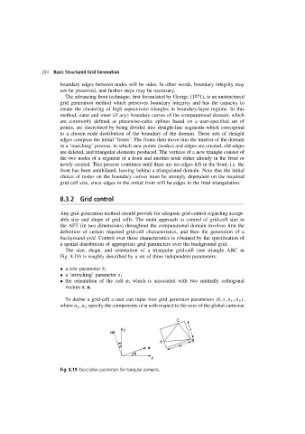
The size, shape, and orientation of a triangular grid-cell (see triangle ABC in
Fig. 8.19) is roughly described by a set of three independent parameters:
• a size parameter δ;
• a ‘stretching’ parameter s;
• the orientation of the cell φ, which is associated with two mutually orthogonal
vectors s, n.
To define a grid-cell a user can input four grid generator parameters (δ,s,n x ,n y ),
where n x , n y specify the components of n with respect to the axes of the global cartesian
C
y d
n
A B
f sd
s
f
x
Fig. 8.19 Descriptive parameters for triangular elements.