
Page 217 - Basic Structured Grid Generation
P. 217
206 Basic Structured Grid Generation
3
P
2
1
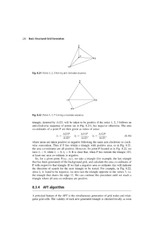
Fig. 8.21 Points 1, 2, 3 forming anti-clockwise sequence.
3
1 2
P
Fig. 8.22 Points 1, 2, P forming a clockwise sequence.
triangle, denoted by 123, will be taken to be positive if the order 1, 2, 3 follows an
anti-clockwise sequence of points (as in Fig. 8.21), but negative otherwise. The area
co-ordinates of a point P are then given as ratios of areas:
23P 31P 12P
l 1 = , l 2 = , l 3 = , (8.16)
123 123 123
where areas are taken positive or negative following the same anti-clockwise or clock-
wise convention. Thus if P lies within a triangle with positive area, as in Fig. 8.21,
the area co-ordinates are all positive. However, for point P located as in Fig. 8.22, we
have l 3 < 0, while l 1 > 0, l 2 > 0. It is clear that, when P lies outside the triangle 123,
at least one area co-ordinate is negative.
So, for a given point P(x P , y P ), we take a triangle (for example, the last triangle
that has been generated) of the background grid, and calculate the area co-ordinates of
P with respect to that triangle. If we find a negative area co-ordinate, this will indicate
the direction of search for the next triangle to be tested. For example, in Fig. 8.22,
since l 3 is found to be negative, we next test the triangle opposite to the vertex 3, i.e.
the triangle that shares the edge 12. We can continue this procedure until we reach a
triangle where all area co-ordinates are positive.
8.3.4 AFT algorithm
A principal feature of the AFT is the simultaneous generation of grid nodes and trian-
gular grid-cells. The validity of each new generated triangle is checked locally as soon