
Page 116 - Basic Well Log Analysis for Geologist
P. 116
LOG INTERPRETATION
ee eee ee eee seen eee ence ec eec eee
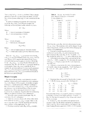
Then a value for S, = 19.4% is calculated. This is already Table 9. Density - Resistivity Crossplot
plotted on Figure 40. As other points are added, you will Data, Morrow Sandstones. Cimmarron
have a better picture of the range of water saturations for the County, Oklahoma, |
well. No. Depth (ft). ppl gnvcc) R,
In addition to plotting true porosity (@) versus deep
! 4.400 2.38 1.7
resistivity (Ripg or Rypg) on a Pickett crossplot, the
2 4.402 2d 2]
following can also be plotted on the vertical (or y) axis:
3 4.410 2.35 1.3
4 4.414 2.42 1.6
At — Atma
5 4.426 2.42 1.8
Where:
6 4.430 2.33 1.0
At = interval transit time of formation
7 4.438 2.30 0.9
Atya = interval transit time of matrix
4,536 2.30 40)
9 4.540 2.30 45
Pma — Pb
100 4.546 2.30 40
Where:
Pma = density of matrix
Py = bulk density of formation
Table 9) on the v axis (Fig. 43) versus the porosity log data
Osnp or Peni (At, py, or by). The resistivity scale can be changed, by any
Where: order of magnitude, to fit the log data without changing the
validity of the graph paper.
Ogyp = sidewall neutron porosity, limestone ¢ units
by, = compensated neutron porosity, limestone @ units 4. Construct a straight line through the most
northwesterly points (Fig. 43), and extrapolate this line
until it intersects the x axis (Fig. 43:6 = 0; and R, = *).
When At — Atyy OF Pma 7 Pp are plotted versus R, (Rig
The straight line defines S, = 1.0. and is called the R,, line.
units (Fig. 43).
or Ryyg). a value for formation matrix (Atya OF Pma) Must be S. Atthe intersection point of the x axis and the R, line
used. Pickett (1972) suggests that whenever At,,, oF Pma- (where S, = 100%; cxample Fig. 43), determine the matrix
selected for the log-log crossplot, is incorrect, the R, line value (Py_ = 2-70 gni/ec) and scale the x axis in porosity
for At — Atjja OF Pma 7 Pp» Versus R, plot will not plot as a
straight line (Fig. 40). but will curve. A geologist should try 6. Calculate a value for Ry from any corresponding set
several matrix values (Aty, OF Oma) Until the Ry, line is of d and R, values by the formula Ry = R,/F On Figure 43,
straight. By such trial and error, a correct matrix parameter R, = 6.0. 6 = 10%, and F= 0.62.15 (F = 87.6),
(Ata OF Pm,) for a formation is determined. Determining
Therefore:
matrix parameters (At,,, OF Pma) is an additional benefit of
the Pickett crossplot technique. R, = R,/F
Ry = 6.0/87.6
Hingle Crossplot Ry = 0.068
The oldest of the resistivity versus porosity crossplot 7. Determine lines of constant S,, based on the formula:
methods. which can be used to determine water saturation Sy = VIR,/R,) for any given value. On Figure 43:
(S,,), is the Hingle (1959) crossplot. As in other crossplot
b&b RR Sy VER S/RD
techniques, a significant benefit of Hingle’s technique ts
10. 6.0 2*%R,= 12 71%
that, even if matrix properties (om, or At,,,) of a reservoir
10 6.0 4x R,= 24 50%
are unknown, you can still determine a value for water
10 6.0 TLR, = 66 30%
a
saturation (S,,). This is also true if reservoir’s water
10 6.0 25* R,= 150 20%
resistivity (R,.) is unknown. The procedure for constructing
a Hingle crossplot to determine water saturation is: Remember that all lines of constant Sy must be constructed
1. Select the correct crossplot graph paper (Fig. 41, so that they converge at the matrix point (d = O and R, = *;
sandstones; Fig. 42. carbonates). Fig. 43). The lines of constant Sy (Fig. 43) are only valid if
2. Seale the x axis on a linear scale, using values taken the R, is constant.
from a porosity log (At. P,, or dy; example, Table 9). Be 8. Evaluate S, values forall the points plotted on the
sure to select the scale so that the maximum porosity log crossplot; make sure the plotted data points are numbered
valucs will plot on the graph paper (Fig. 43). (Table ¥ and Fig. 43) to avoid confusion. In Figure 43, the
3. Plot deep resistivity values (Ry_g or Rppg; example. water-bearing Morrow sands from 4,400 to 4,438 tt (points