
Page 60 - Basic Well Log Analysis for Geologist
P. 60
RESISTIVITY LOGS
RR, = resistivity of the flushed zone
a = constant
a= 1.0 for carbonates
solve tor F:
a == 0.62 for unconsolidated sands
a = 0.81 for consolidated sands
m = constant
F Ring
There fore m = 2.0 for carbonates and consolidated sands
m = 2.15 for unconsolidated sands
Ryo
a Sxo7 Syo = Water saturation of the flushed zone
cm Rat
Syo = 1.0 minus residual hydrocarbon saturation
solve for porosity (6): (RHS). See Table 5 for examples.
F = formation factor
o= [Raed | m
(Syo¥
Review - Chapter III
Where:
1. Resistivity logs are used to: (1) determine
& = formation porosity
hvdrocarbon- versus water-bearing zones; (2) indicate
Ruy = resistivity of mud filtrate at formation
permeable zones; and (3) determine resistivity porosity.
temperature
2. A formation’s resistivity can be measured by either
induction or clectrode (Laterolog*, normal, Lateral,
Table 5. Percentages of Residual Hydrocarbon Saturation
spherically focused logs, Microlog*, Microlaterolog* . and
asa function of hydrocarbon density and porosity
Proximity*) logs.
(modified after Hilchie, 1978).
3. Induction logs (induction electric log or Dual
oe — APPGravity = RHS% S., %. _
Induction Focused Log) should be run in non-salt saturated
Gas 40 to 5 60 to 95 drilling muds (where Ryyp > 3 Ry).
High gravity ot] 40 to 50 10 to5 90 to 95 should be
4. Laterologs* or Dual Laterologs* with R,, XO
Medium gravity oil — 20 to 40 20 to 10 80 to 90 run in salt-saturated drilling muds (where Ry = Ry).
to
20
80_
to
30020
Low gravity oil 70 3. By use of tornado charts, the deep resistivity log on
_10
Porosity RHS% Syo% either the Dual Induction Focused Log or the Dual
%
25 to 35 30 70 Laterolog® with R,, can be corrected for the effects of
Invasion to determine amore accurate value of true
Iwo20 0 IS BS formation resistivity (R,).
6. Most minerals which make up the matrix of the rock
and the hydrocarbons in the pores are non-conductive.
Therefore, the ability of the rock to transmit an electric
a I [~ current is almost entirely a function of the water in the
iA rock's pores.
[re AMPLIFIER
Mo AND
OSCILLATOR
HOUSING
iv RECE: VER
— _t JcOIk SX
- ao
| RECEIVER 4
_ AMPLIFIER GROUND
“TT / Loon/ an
FOUCAULT i A
CURRE ° ( |
CURRENT | | i !| FORMATION
a __ TRANSMITTER “h
a
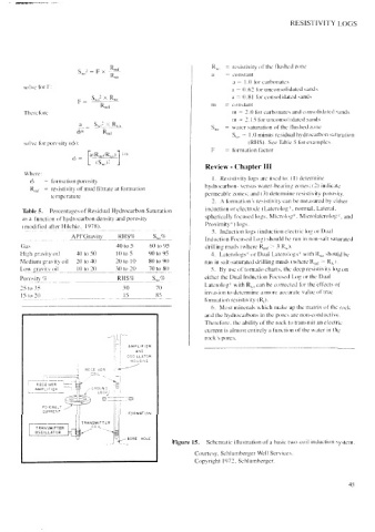
Figure 15.) Schematic illustration of a basic two-corl induction system.
Lok
TRANSMITTER |
OSCILLATOR
BORE HOLE
Courtesy, Schlumberger Well Services.
Copyright 1972, Schlumberger.
fs wa